A review and teardown analysis of the WITRN (维简) W96Pro portable fan, including a circuit analysis.
I recently bought a small fan that connects and is controlled over Bluetooth, offers percentage-based speed adjustment, 18W fast charging, and a 4800mAh battery (a 21700 cell). Its USB-C port supports both input and output, so it can even double as a power bank. In this article, I'm taking it apart to analyze the circuitry.
Gongtian F95D mini fan teardown analysis: https://blog.zeruns.com/archives/953.html
Other teardown articles: https://blog.zeruns.com/tag/拆解/
Teardown video: https://www.bilibili.com/video/BV1Gft56TEYr/
Specifications
- Product name: SDF software-defined smart fan
- Product model: W96Pro
- Motor type: Sinusoidal-wave DC brushless motor
- Motor drive power: 10W (12W peak output)
- Battery type: 21700 lithium-ion cell
- Supported battery: 3.6V lithium cell (approx. 4.2V when fully charged)
- Input power: 18W Max
- Input voltage: DC 5~12V
- Input current: 1.5A@12V, 2A@9V, 3A@5V
- Input fast-charge protocols: PD, QC, FCP, AFC, DCP
- Dimensions: 150x110x40mm
Purchase link: https://s.click.taobao.com/RYC0Mkj
Fan Photos
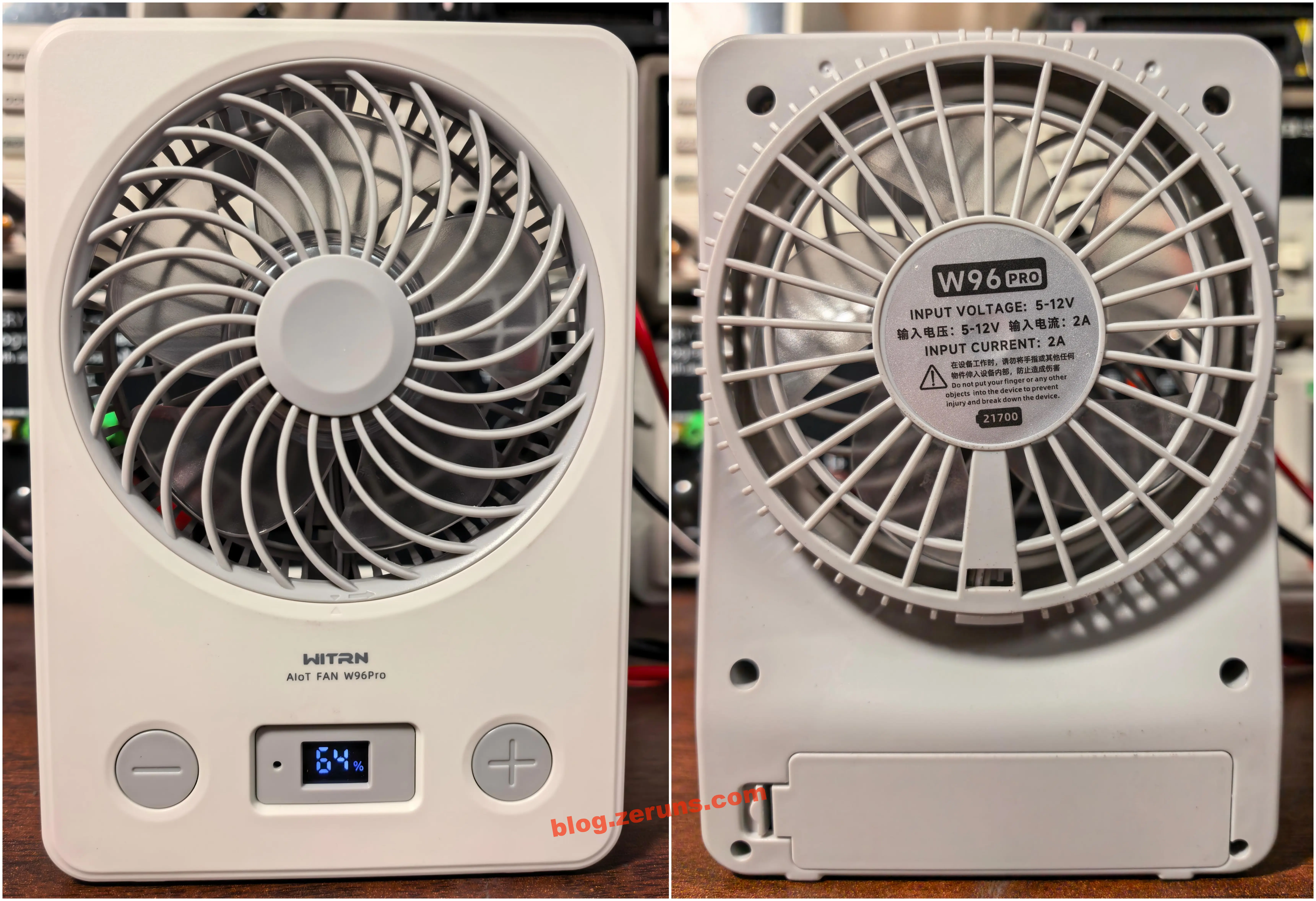
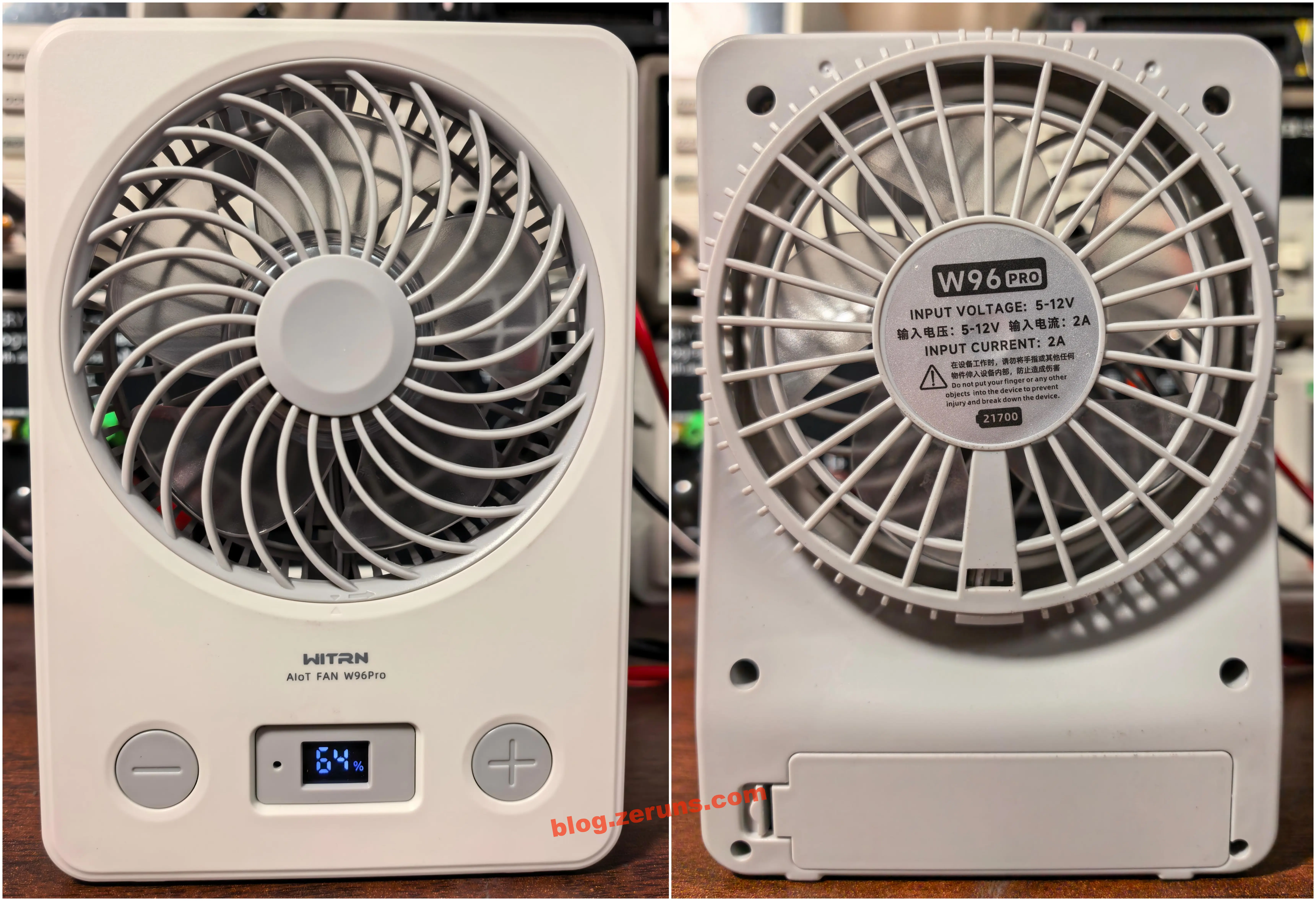
Front and back views of the fan. There are two buttons on the front:
- The left − button: with the display asleep, one press shows the battery percentage, then shows level 0; while the fan is running, a single press lowers the speed level; press and hold decrements the level in 1% steps; while running, double-press sets a shutdown timer, and double-pressing again cycles through the timer durations.
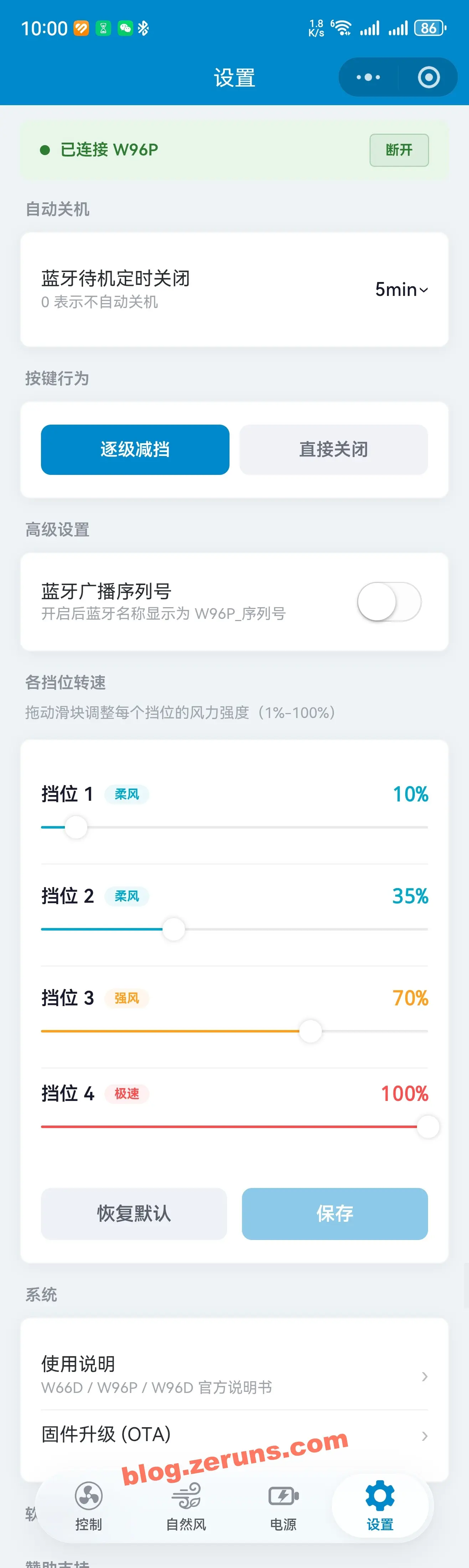
- The right + button: with the display asleep, one press powers the fan on into level 1 (10%), and further presses raise the level (the default levels are 10%, 35%, 70%, and 100% — the percentages of these four levels can be modified with the companion app); press and hold increments the level in 1% steps; double-press toggles Natural Wind mode.
In the middle there's a Bluetooth indicator LED (blue) and a 7-segment LED display (white). The display is three digits wide, but the leftmost digit can only ever show the number "1"; at the far right of the display there's also a lightning-bolt icon (lights up green while charging) and a "%" symbol.
On the back of the fan there's a label in the center, printed with specifications in both Chinese and English:
- W96 Pro
- INPUT VOLTAGE: 5-12V
- 输入电压: 5-12V 输入电流: 2A
- INPUT CURRENT: 2A
- 在设备工作时,请勿将手指或其他任何物件伸入设备内部,防止造成伤害
- Do not put your finger or any other objects into the device to prevent injury and break down the device.
At the bottom of the rear is the battery compartment, which takes 21700 size NMC lithium-ion cells.
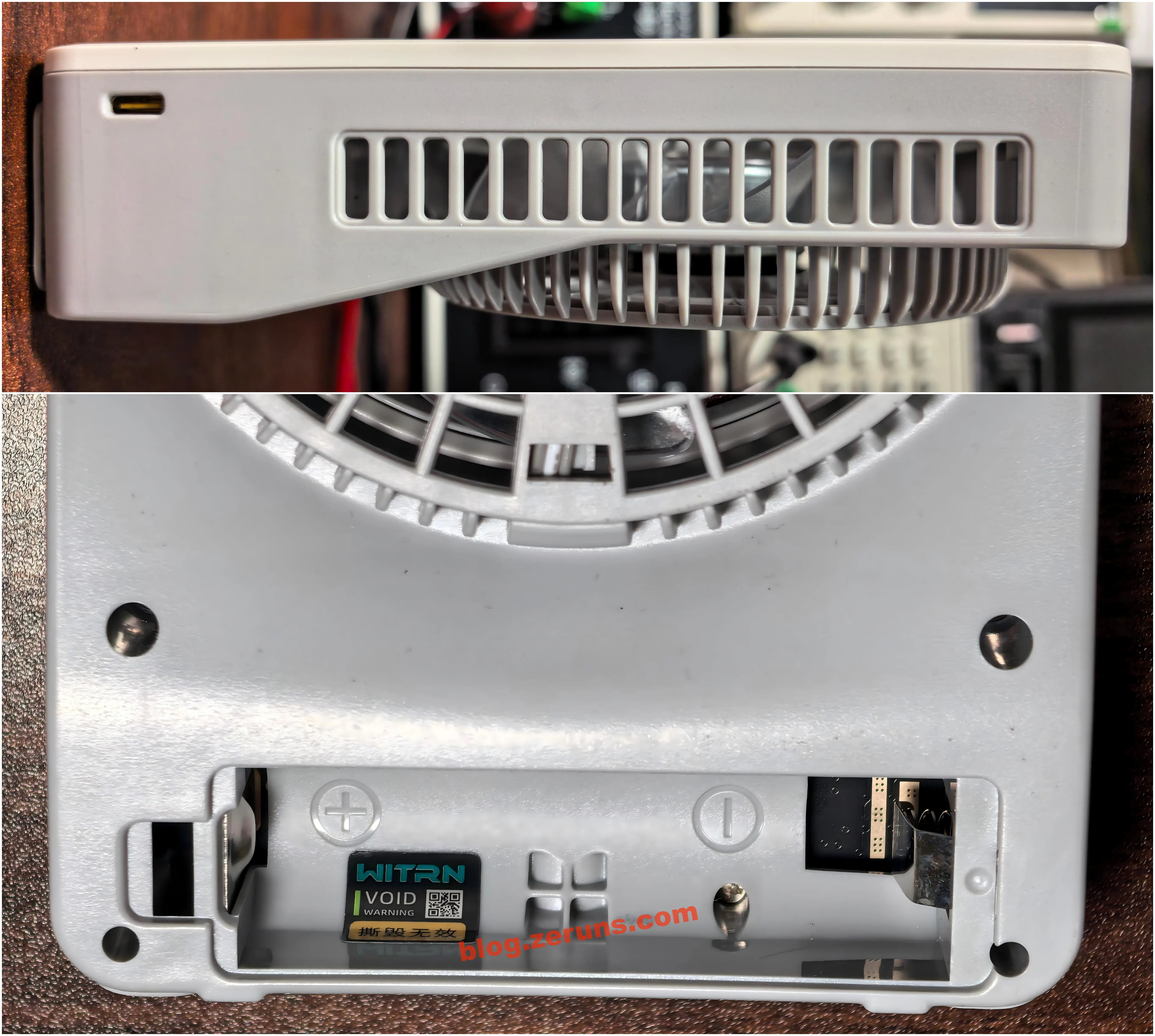
The right side of the fan houses the Type-C charging port. This USB-C port is bidirectional, so the fan can also be used as a power bank. The screw holes inside the battery compartment are covered with tamper-evident stickers that read "void if torn".
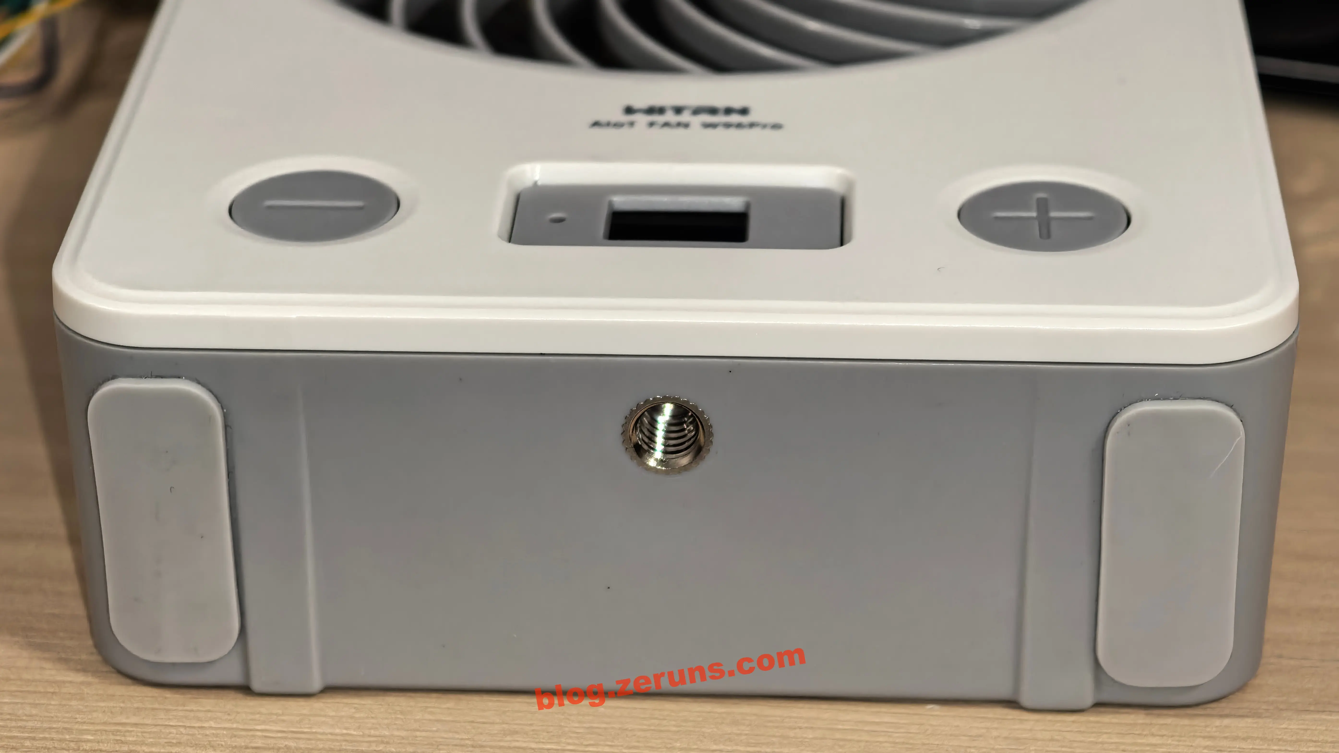
The base also has a 1/4-inch threaded mount, so the fan can be fixed onto a tripod. It comes with two anti-slip pads as well (two self-adhesive non-slip pads are included in the box — I stuck mine on the bottom).
At full speed, the fan won't stand upright on its own and will topple over. If you don't plan to use a tripod, I'd suggest sticking the anti-slip pads onto the side of the fan and letting it rest on its side.
Charging Power and Heat Test
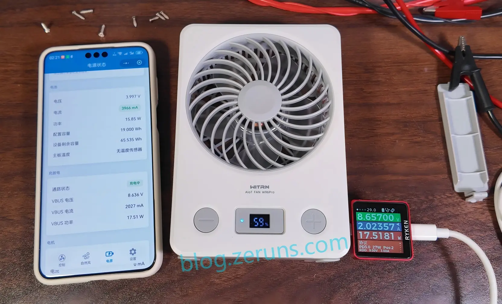
I used a 65W fast charger that supports the PD protocol. With the fan's battery at 59%, measured charging power was around 17.5 watts, requesting 9V.
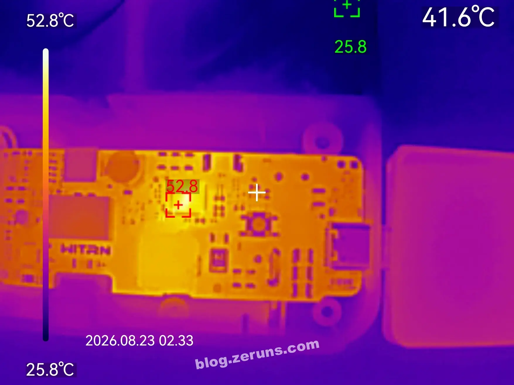
Thermal image of the front of the PCB after ten minutes of charging: ambient temperature around 26°C, and the charging IC ran at about 52.8°C.
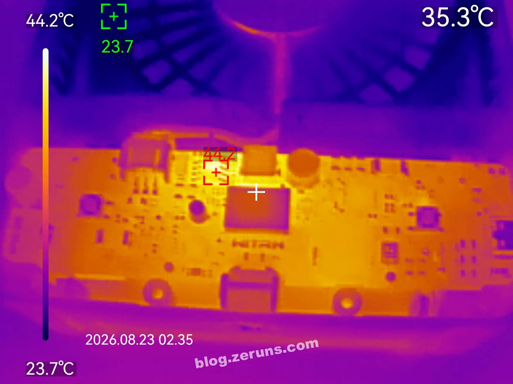
Thermal image of the front of the PCB after running at the 100% level for ten minutes: ambient temperature around 26°C, and the boost converter supplying the motor ran at about 44.2°C.
Speed Measurement
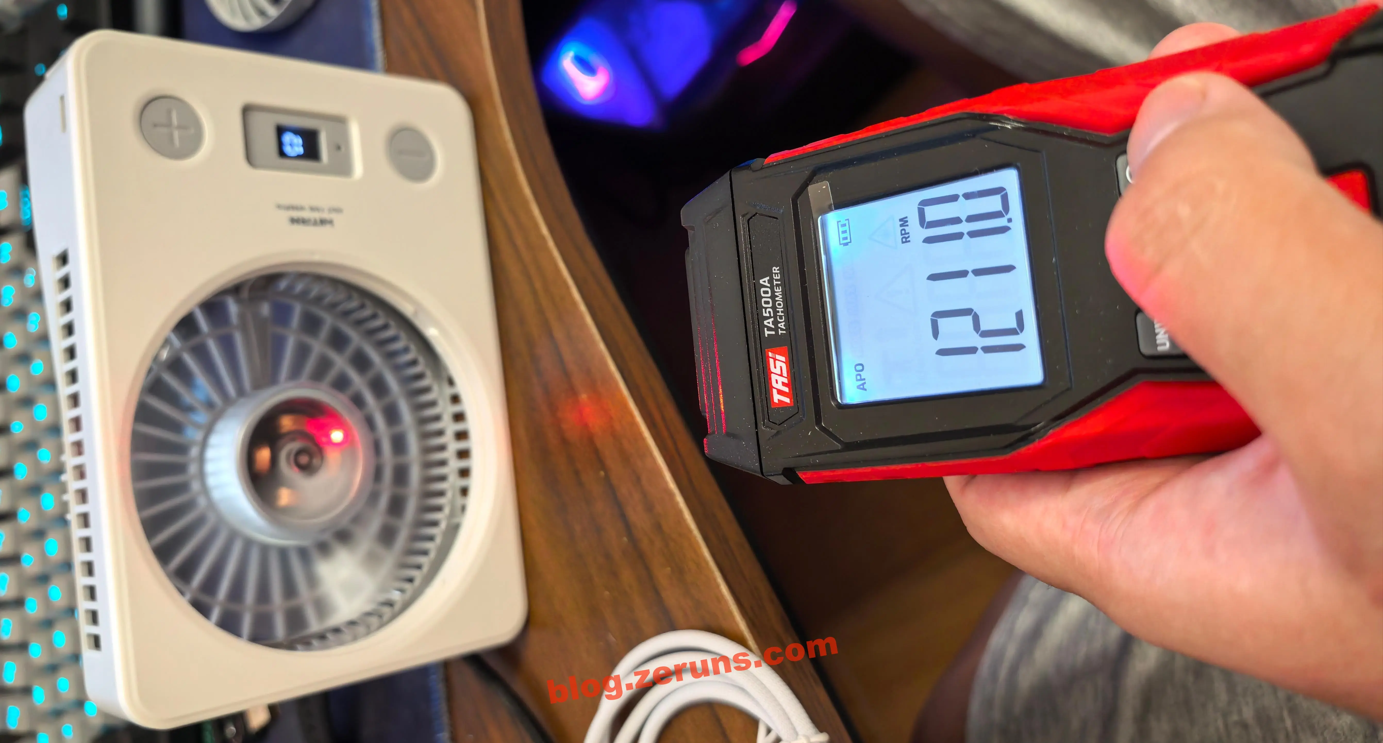
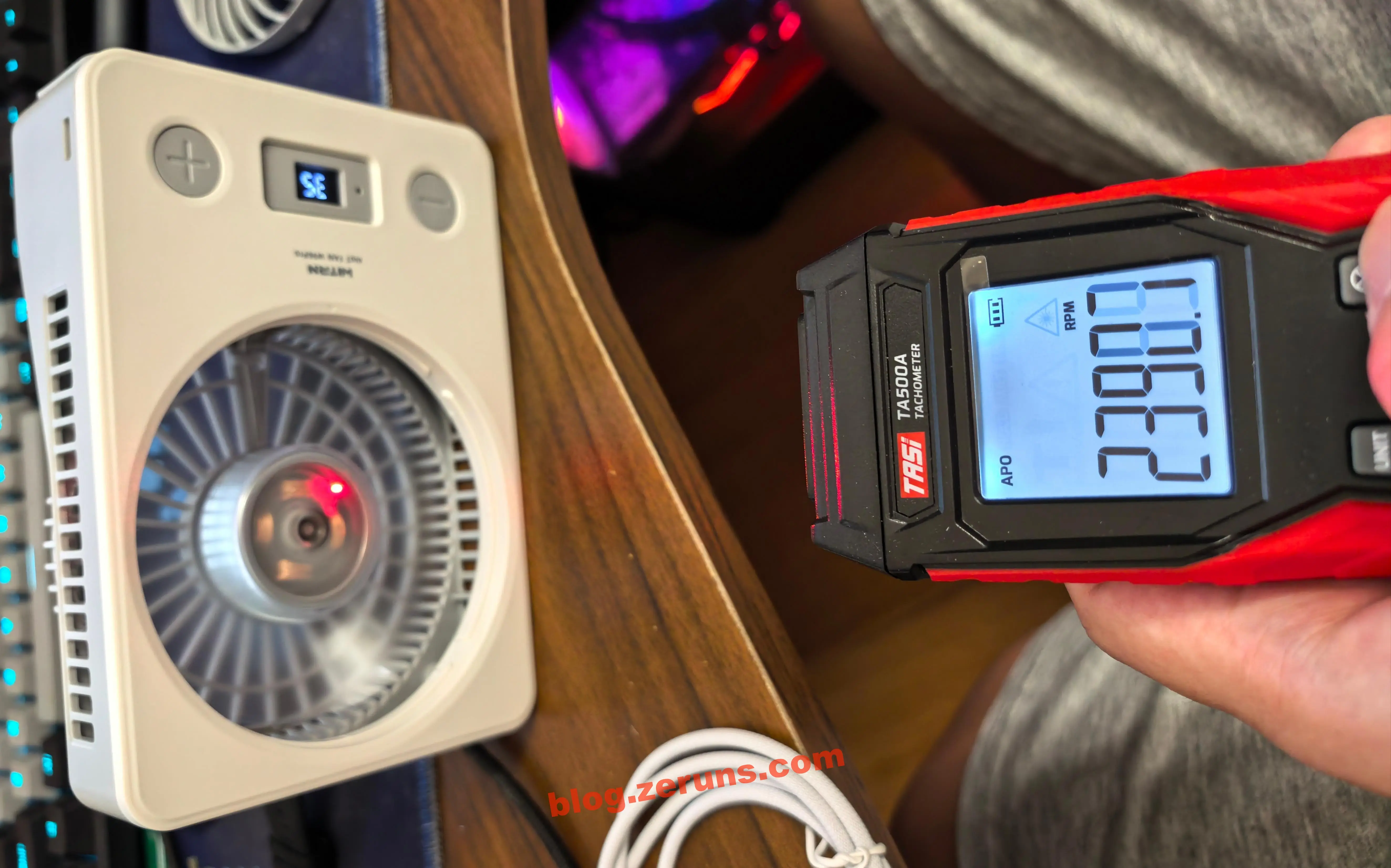
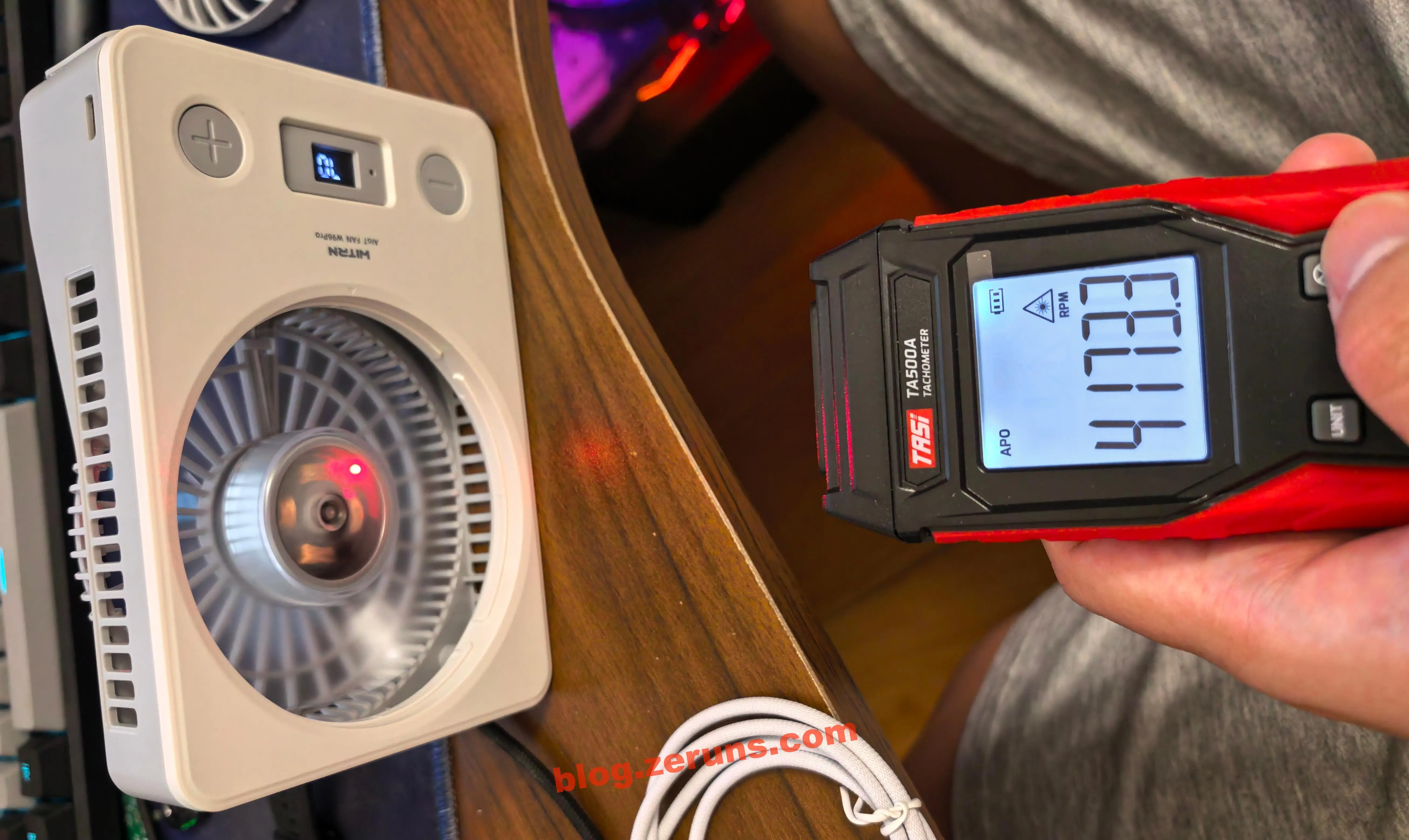
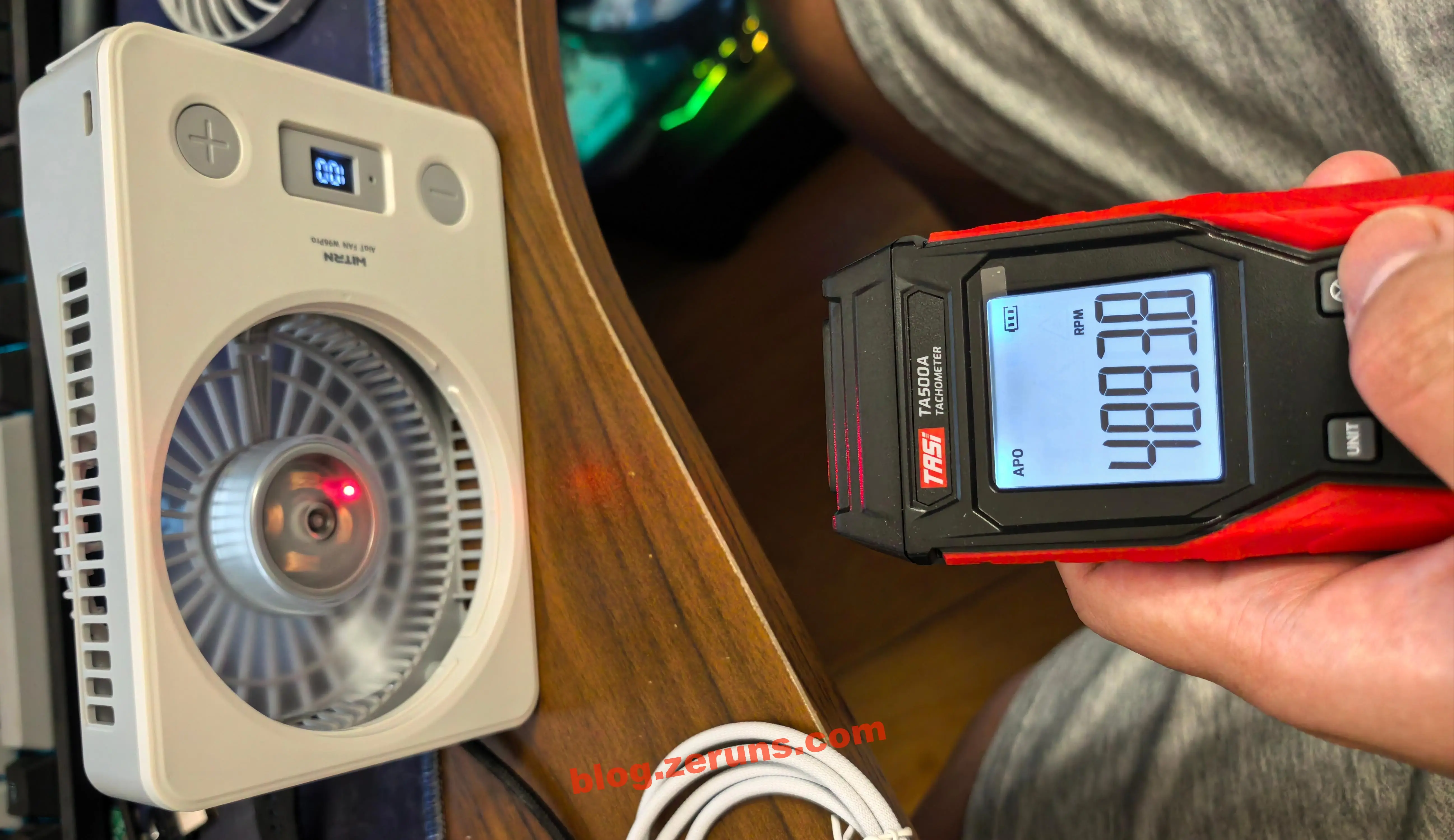
I used the TASI TA500A laser tachometer to measure fan speed — first you have to stick a reflective sticker onto one of the blades.
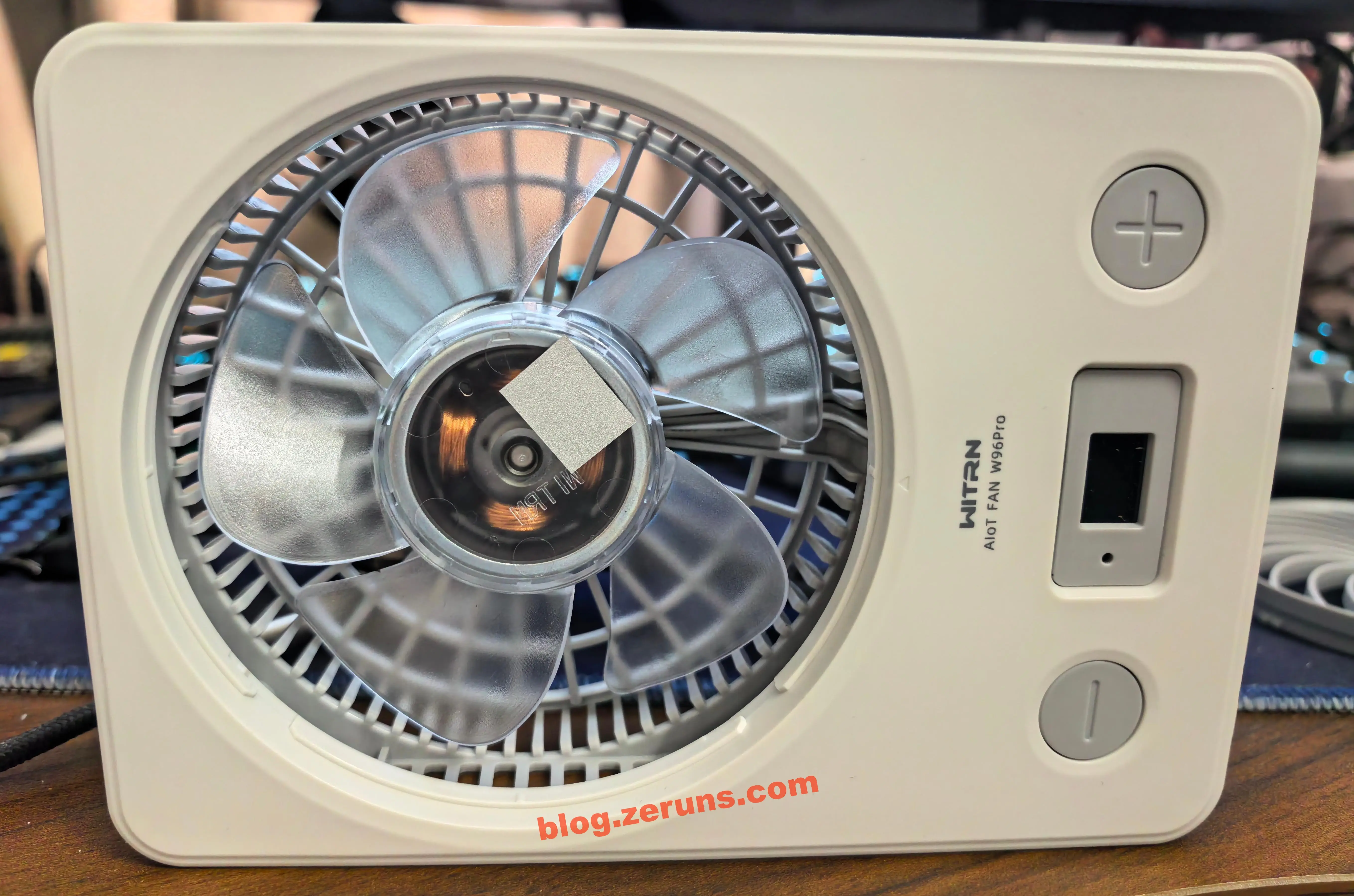
Level 1 (10%) speed: 1211 RPM. (RPM: revolutions per minute)
Level 2 (35%) speed: 2390 RPM.
Level 3 (70%) speed: 4173 RPM.
Level 4 (100%) speed: 4893 RPM.
Motor Power Testing
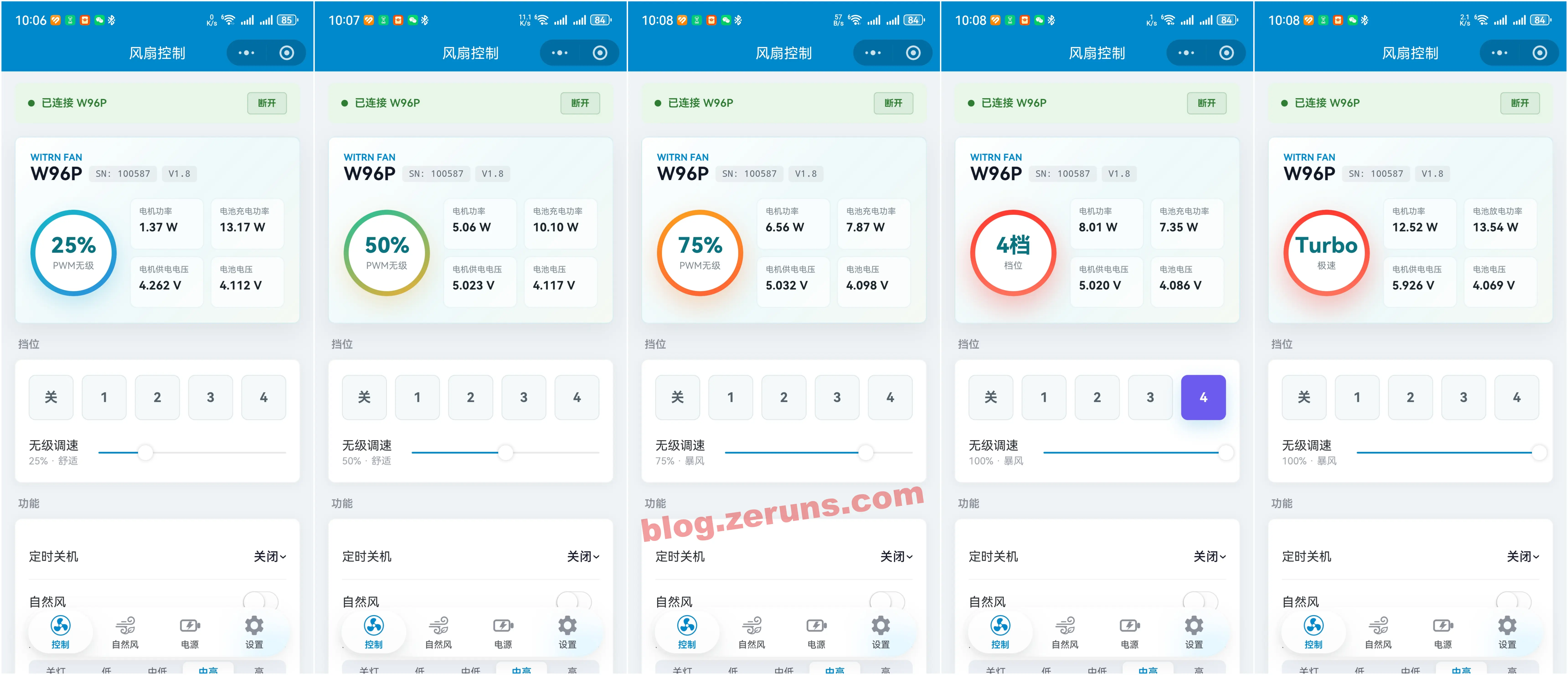
The data in the table below was obtained by connecting to the fan via Bluetooth from the companion mini program. (As a sanity check, I measured the voltage across the motor's current-sense resistor with a multimeter on its millivolt range and derived the current by dividing by the resistance — the result matched the mini program readings closely. The motor voltage measured with the multimeter also matched what the app reported, so I simply took the numbers straight from the mini program.)
| Level | Motor Power | Motor Voltage |
|---|---|---|
| 25% | 1.37 W | 4.26 V |
| 50% | 5.06 W | 5.00 V |
| 75% | 6.56 W | 5.00 V |
| 100% | 8.01 W | 5.00 V |
| Turbo | 12.52 W | 5.90 V |
The motor is fed by a boost DC-DC converter: below the 50% level it supplies the motor with 4.2V, at 50% and above it supplies 5V, and Turbo mode gets 5.9V.
Fast-Charge Output Testing
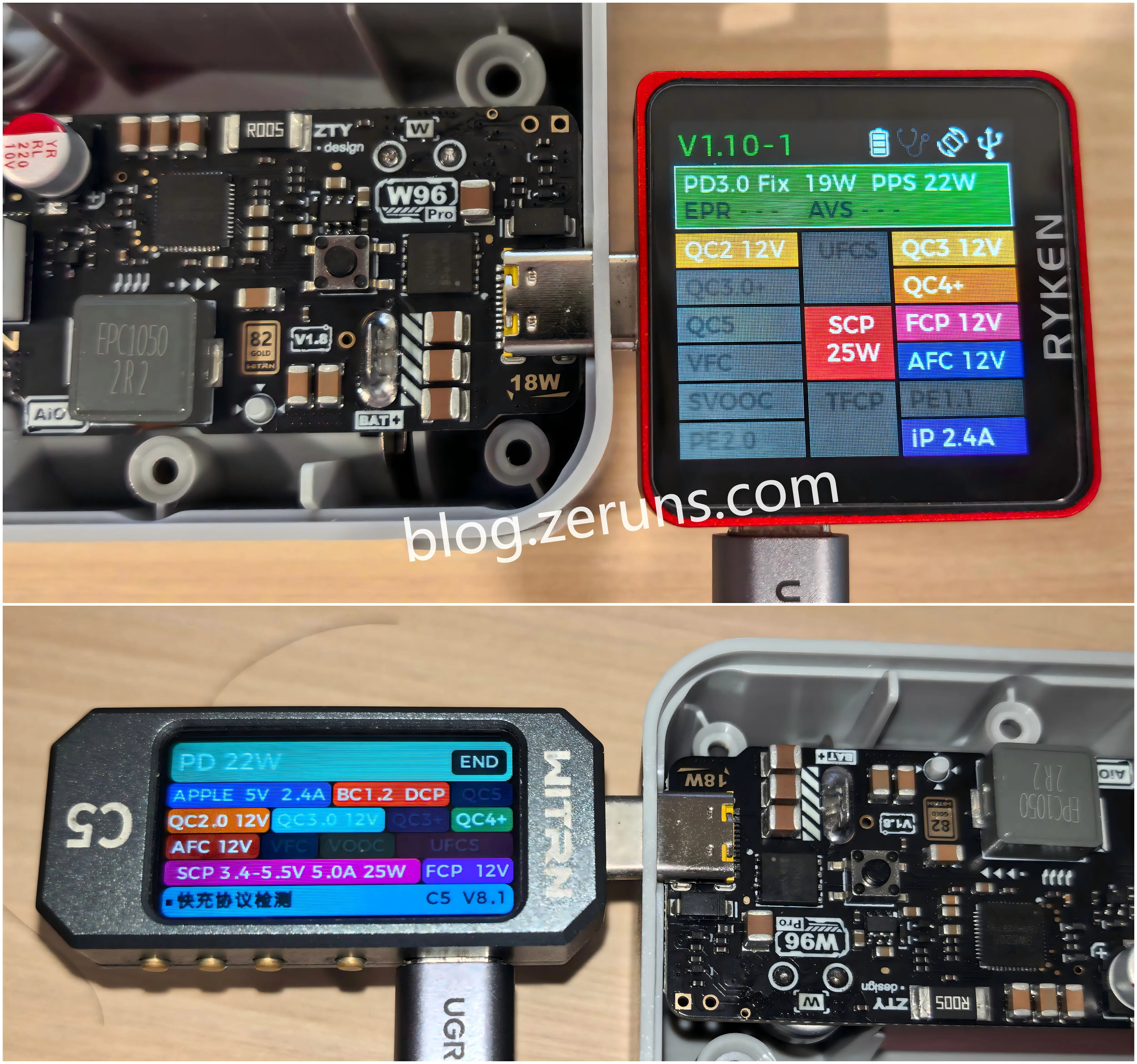
Next I used an RK-X3 Pro fast-charge tester and a WITRN C5 detector to probe which fast-charging protocols the fan's USB-C output supports: it handles PD (22W), SCP (25W), QC, FCP, AFC, and other protocols.
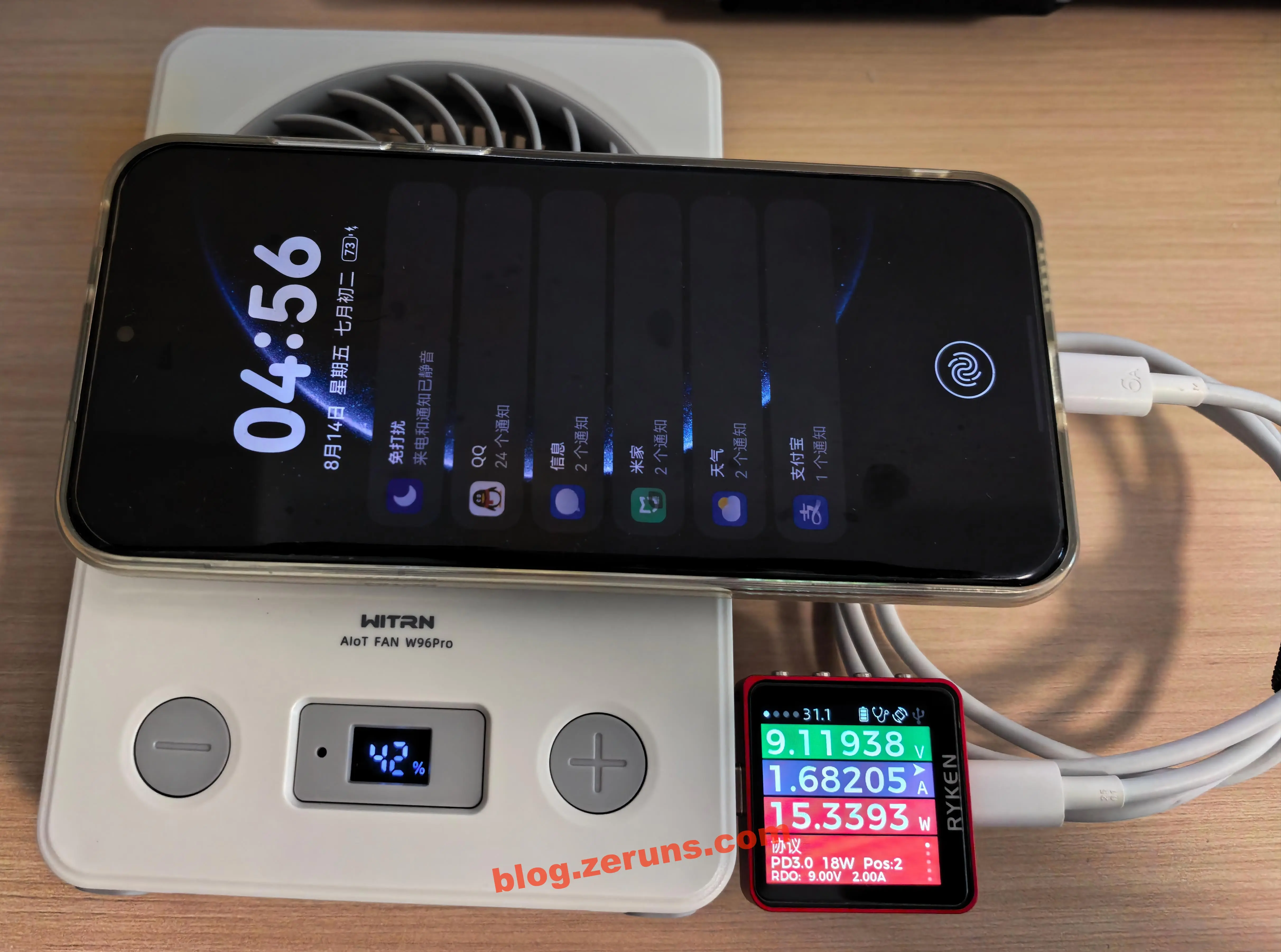
Using the fan's USB-C port to charge a Huawei Pura70Pro+, charging power came out at around 15 watts; the negotiated protocol was PD 3.0 at 18W, requesting 9V.
Companion Mini Program
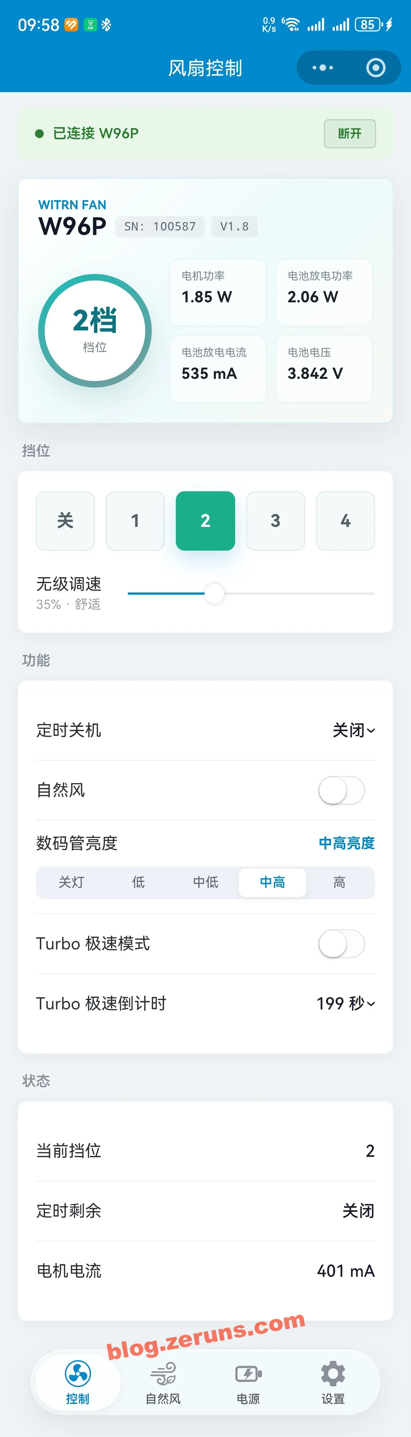
The companion WeChat mini program is divided into four pages: Control, Natural Wind, Power, Settings.
The card at the top of the Control page lets you choose four parameters to display. Available readouts include PWM, shutdown timer, battery level (%), battery voltage, battery current, battery power, configured battery capacity, board temperature (this unit apparently doesn't support it — the temperature always shows 0), charge/discharge status, VBUS voltage, VBUS current, VBUS power, charging IC temperature, motor current, motor supply voltage, motor power, motor status, and more.
You can set the fan level directly or adjust it by percentage, and configure things like the shutdown timer and the brightness of the 7-segment display.
The Natural Wind page lets you configure the curve used by Natural Wind mode.
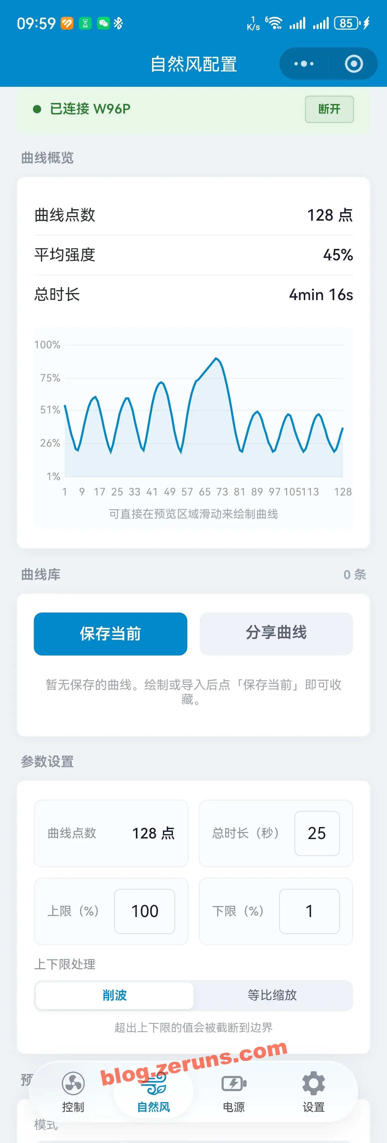
The Power page displays all kinds of power-related information — voltage, current, power, etc. You can set the battery capacity (used by the coulomb counter to calculate the remaining charge as a percentage) and configure fast charging (you can enable or disable specific fast-charge protocols, and set the voltages requested or offered).
Note: the firmware and/or companion mini program appear to have a bug. New units ship with compatibility issues in their fast-charge output — among the devices I had on hand, only Huawei's Mate70Pro+ and Pura70Pro+ phones could trigger fast charging; the vivo X100 and many other devices could not trigger the fan's charging output at all, and probing the fast-charge protocols with the WITRN CC meter returned no results. Setting every protocol to the "all-on compatibility mode" on the mini program's Power page made no difference — but after switching to Expert Mode, finding the "Type-C Role" option, and changing Only Sink to DRP, everything returned to normal and fast-charge protocol detection worked again.

The Settings page lets you customize the speed percentage of each level and upgrade the firmware.
Teardown
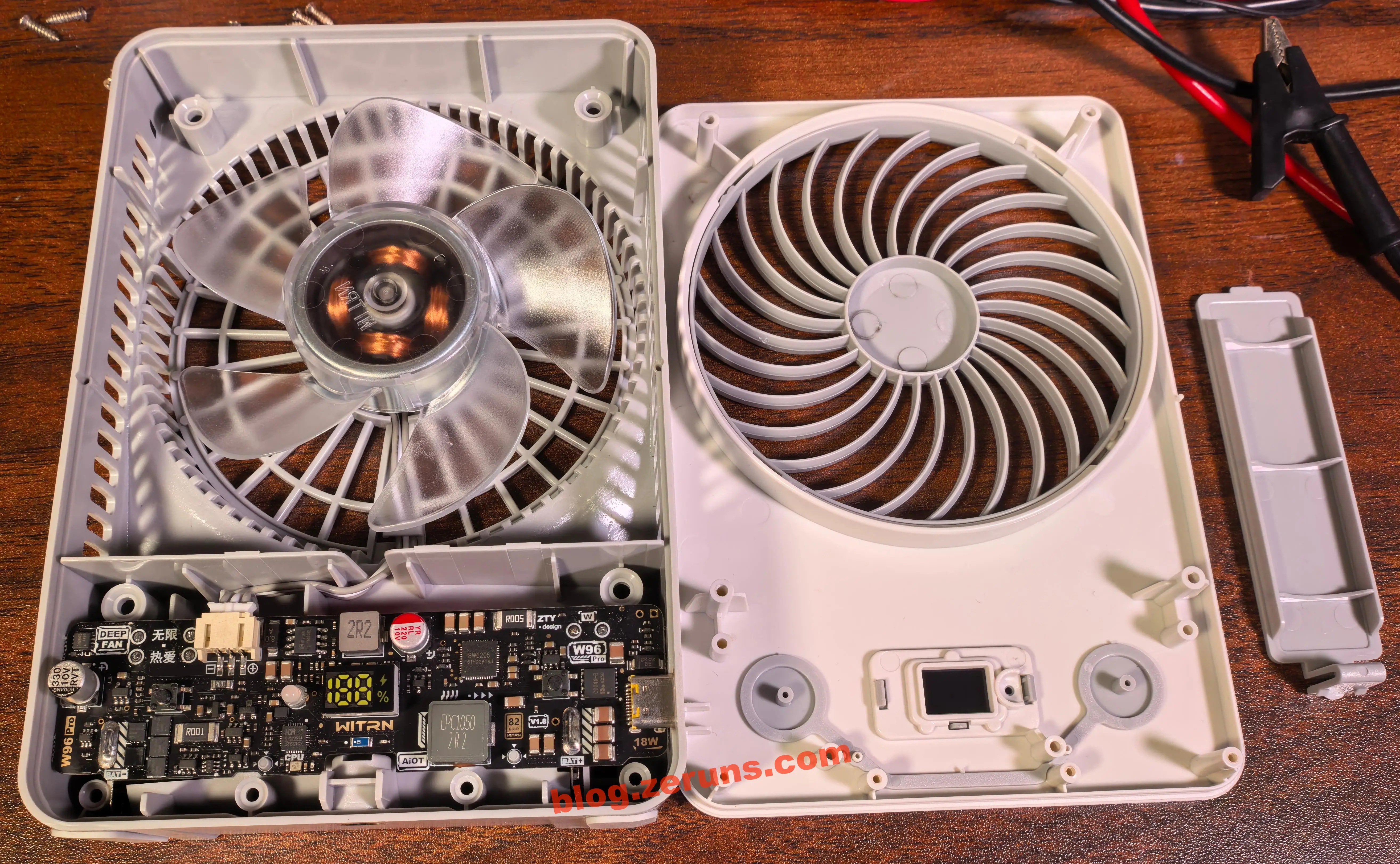
Unscrew the six Phillips screws on the back of the fan (four on the outside and two inside the battery compartment; one of the compartment's screw holes is covered by a tamper seal), and the front panel of the fan comes off. The motor has four sets of stator windings, so it's most likely a two-phase BLDC (brushless DC) motor — though it could also be single-phase. To know for sure you'd have to pull off the rotor and look at how the driver board routes to the coil windings. The cable from the main board to the motor has 3 conductors.
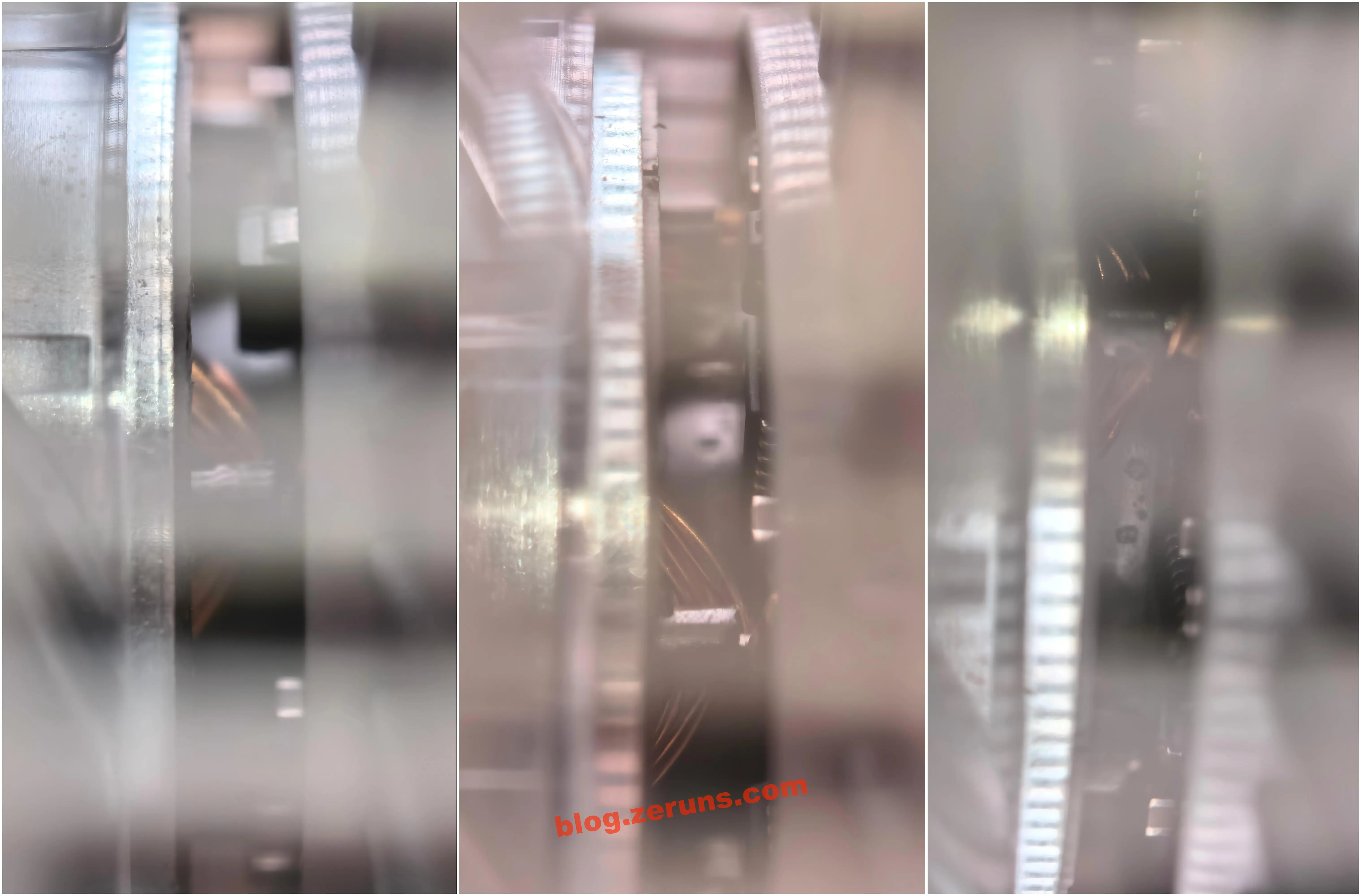
Viewed from the side, you can see this motor carries its drive circuitry underneath. Like the brushless motors in cooling fans, it has an integrated driver — but strictly speaking, the driving scheme is different: ordinary cooling fans essentially all use square/trapezoidal-wave six-step commutation, whereas this unit claims sinusoidal-wave drive, which is a step above. This one has 4 coil sets. The official marketing term is "sinusoidal-wave DC brushless motor", meaning the drive waveform is sinusoidal — i.e., SPWM modulation. Verifying this would require removing the motor and measuring the phase-current waveform with an oscilloscope.
(There's a contradiction worth pointing out here: sinusoidal drive is generally associated with three-phase motors, whose coil counts are multiples of three, whereas this one has only 4 coils — closer to a two-phase or single-phase four-pole arrangement. That said, a two-phase motor can equally well be driven with two sine waves offset by 90°, which also yields smooth torque, so "4 coils + sine wave" isn't inherently contradictory. But whether it's really two-phase, and whether the drive is truly sinusoidal, would have to be confirmed by scoping the waveforms. Since I still intend to keep using this fan, I'm not going to strip the motor down any further.)
Advantages of sinusoidal-drive DC brushless motors over other ordinary brushless motors:
- Smoother torque and less vibration: sinusoidal currents stay in phase with the back-EMF, giving continuous torque without steps and steadier operation
- Lower noise: none of the abrupt high-frequency current transitions and harmonics of square-wave commutation — electromagnetic noise drops noticeably, which matters most for a portable fan
- Higher efficiency and less heat: harmonic losses are reduced, so temperature rise is lower for the same output power
- Better low-speed behavior: stable, judder-free rotation at low levels suits quiet operation
- Finer speed control: combined with PWM plus regulated voltage from the boost stage, near-stepless adjustment is achievable
- The trade-off: more complex drive algorithms and a costlier driver board
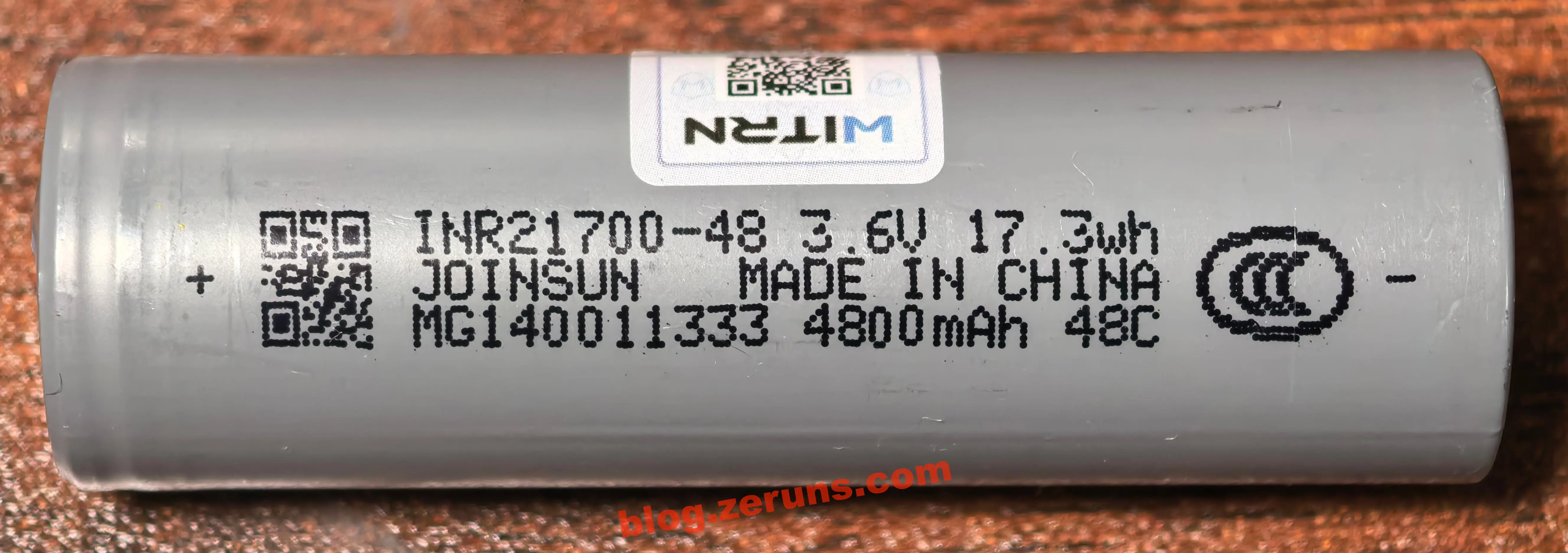
The supplied battery is a JOINSUN INR21700-48 cylindrical NMC lithium-ion cell, model code 48C (digital/storage type), rated capacity 4800mAh, nominal voltage 3.6V, energy 17.3Wh, sized per the 21700 format (about 21mm diameter × 70mm tall; measured 21.7 × 70.8mm), with a China CCC (compulsory certification) mark printed on the jacket.
Key specifications of the JOINSUN INR21700-48C (checked against the datasheet / official website):
- Cathode material: pure ternary NCM 811 (NMC) — ternary lithium
- Capacity: nominal 4800mAh (minimum 4700mAh); nominal voltage 3.6V, energy 17.28Wh (≈17.3Wh)
- Charge specifications: maximum charge voltage 4.2V; charge current 0.5C (2.4A), maximum 1C; discharge cutoff 2.5V
- Discharge rate (48C digital type): continuous 2C (9.6A), maximum pulse 4C (approx. 19.2A)
- Internal resistance: ≤22mΩ; weight: approx. 69–71g
- Cycle life: at 80% DoD @25°C, ≥400 cycles at 2C discharge, ≥500 cycles at 1C discharge
- Certifications: UL / FCC / CE / RoHS / IEC / CB / CCC (3C) / PSE / UN38.3 / MSDS
- Target applications: the official site explicitly lists portable fans, power banks, small appliances, electric toothbrushes/massage guns, and similar consumer electronics
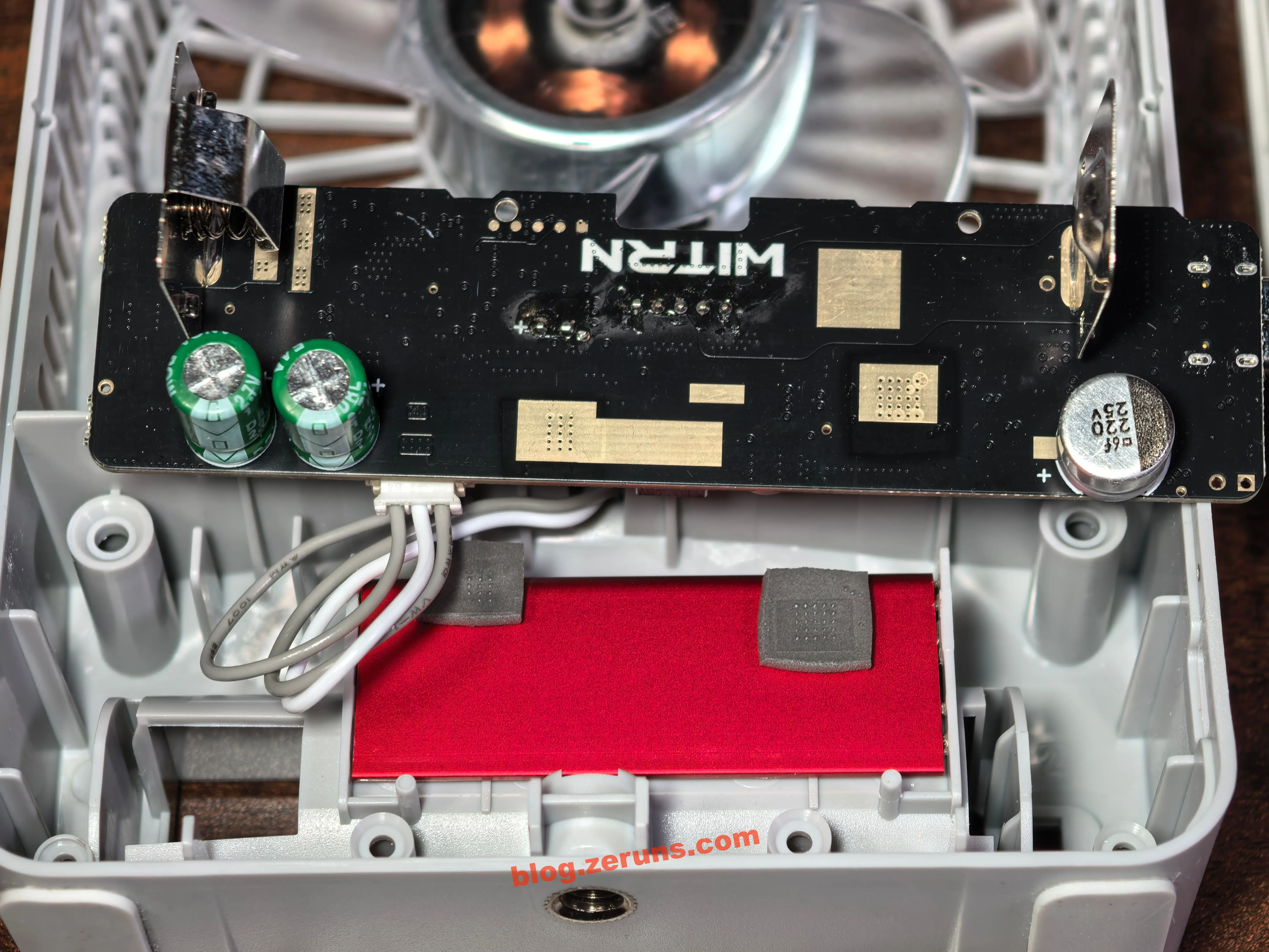
With the main board removed, you can see through-hole battery-contact tabs soldered onto the underside of the board; there's a WITRN silkscreen in the middle of the PCB; and several areas of the solder mask have been opened on the board for heat dissipation from the fast-charge chip and the boost chip;
the board uses an ENIG finish (more expensive than HASL tin plating; its advantages are good surface flatness, oxidation resistance, and corrosion resistance — gold is chemically stable, so unlike HASL boards whose solderability degrades with long storage due to oxidation, ENIG boards keep well — longer shelf life, higher assembly yield, and better contact reliability);
at the lower-right corner of the board there's a 220μF/25V solid polymer capacitor connected in parallel on the USB-C input side, used for energy storage and filtering;
in the battery bay area underneath, there's an aluminum plate acting as a heatsink, with two thermal pads stuck to it aligned with the fast-charge chip and the boost chip regions of the PCB, spreading heat from the chips across the whole plate.
There's flux residue around the through-hole pads of the 7-segment display and the LEDs; the through-hole parts on this board were evidently hand-soldered afterwards, and the residue wasn't cleaned off.
Flux residue can cause problems: in humid environments it absorbs moisture and lowers surface insulation resistance, producing leakage currents between adjacent pads; if the flux contained active ingredients (halides/organic acids), long-term residue can also corrode solder joints and copper traces; in extreme cases, under the combined action of bias voltage and moisture, electrochemical migration (ECM) can occur, growing metallic dendrites between pads and eventually causing shorts. Sticky residue also tends to collect dust, further increasing leakage risk.
Two fair caveats, though: first, production boards today generally use no-clean flux, whose residues are inert and essentially non-conductive — skipping the wash after soldering is standard industry practice, not a process defect; second, these residues sit near the display and LED driver pads, where signal voltages are low and driving impedance is low, so even slight leakage wouldn't affect operation. So this residue is mostly a cosmetic issue with very little practical risk — something you could clean up in passing (with PCB cleaning solution or anhydrous alcohol) but hardly worth faulting the manufacturer for.
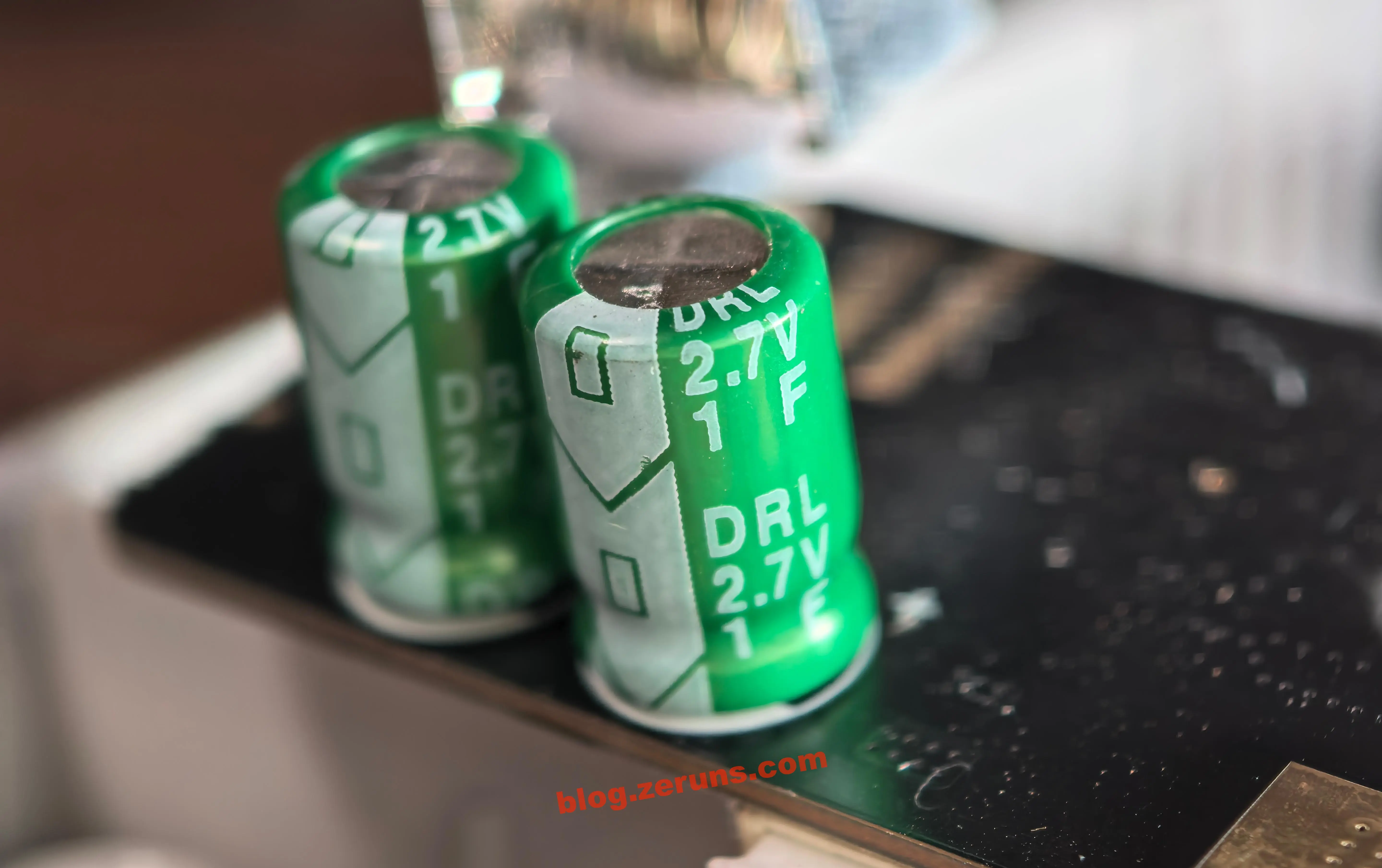
On the left side of the board's underside are two 1F/2.7V supercapacitors; the two capacitors are wired in series and connected in parallel across the battery terminals.
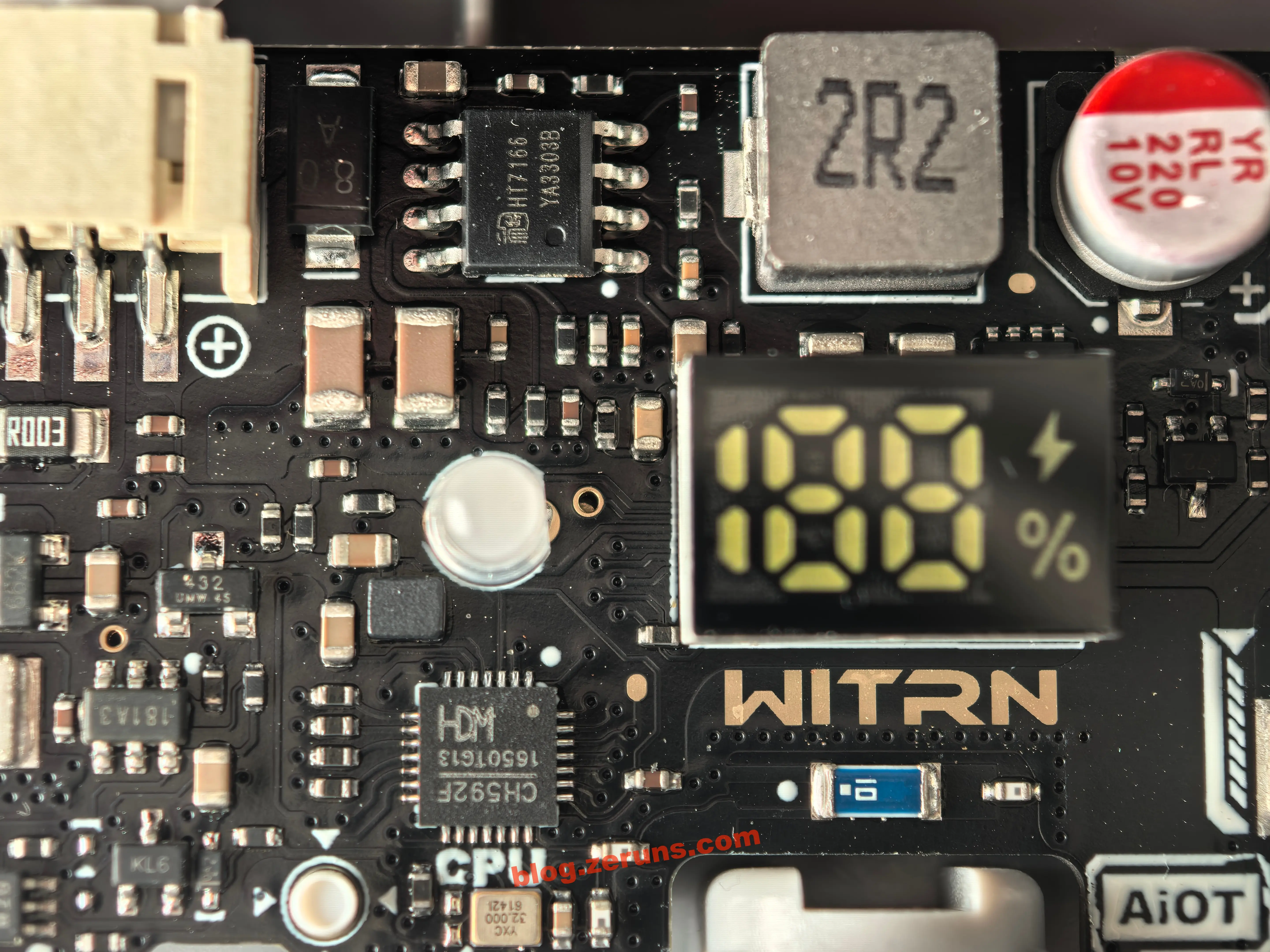
On the front of the main board: the model W96 Pro is printed at top right, version V1.8 at lower right, 18W is marked below the Type-C connector (on a solder-mask opening), the 7-segment display sits in the middle of the board with WITRN marked beneath it (again on a solder-mask opening), and the blue component further below should be a SMD ceramic antenna serving as the MCU's Bluetooth antenna.
The fan motor socket appears to be PH2.0-3P; the wire order from left to right (left to right in the photo below) is: PWM control line, motor supply negative, and supply positive.
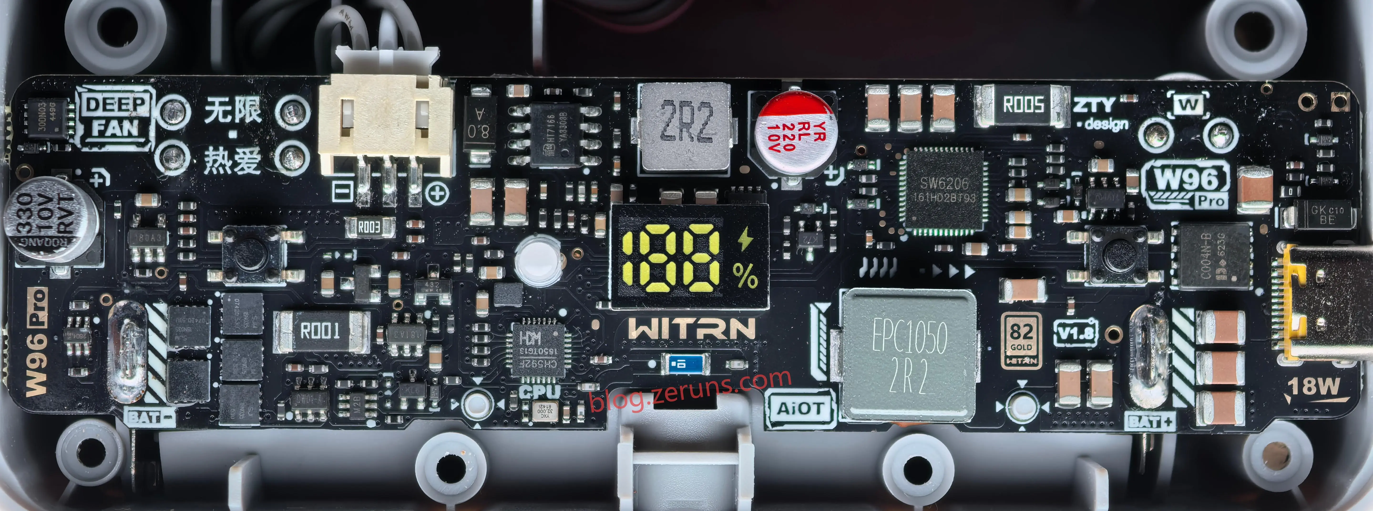
First, the charging circuit. The charging/power-management IC is the SW6206, a multi-protocol bidirectional fast-charge power bank SoC from Zhuhai iSmartWare. It's not the more common Injoinic IP5353 solution — the SW6206 comes in a larger package (QFN48, 6×6mm) and integrates more: a single chip handles USB-C fast-charge input, high-current lithium battery charging, and battery gauging.
Key specifications of the SW6206 (AI-generated):
- Core functions: multi-protocol bidirectional fast-charge power bank SoC, integrating a 5A high-efficiency switching charger (96% efficiency), 22.5W synchronous boost output (95% efficiency), fuel gauge (built-in coulomb counter + 12-bit ADC), LED driver, and Type-C logic (try.SRC)
- Charging/discharging: charge current up to 5A; supports 4.2/4.35/4.4/4.5V batteries, with NTC/JEITA temperature control (reduced current when cold, reduced voltage when hot, shutdown when overheated — though the actual circuit apparently has no NTC resistor fitted); 400kHz switching frequency, needing only a 2.2µH inductor
- Fast-charge protocols: input PD3.0/2.0, AFC, FCP, SCP, PE; output PPS/PD/QC4+/QC3/QC2/AFC/FCP/SCP/PE2/SFCP
- Interfaces: I2C; external power-FET gate drivers GATEA/B/C/L
Below the SW6206 is its companion inductor; together with the MOSFETs built into the charging IC it forms a buck-boost converter — buck (step-down) mode when charging, boost (step-up) mode when outputting from the C port. The inductor is an EPC1050-2R2, a molded one-piece power inductor from the EPC series by Shenzhen Sntengwei.
Key specifications of the EPC1050-2R2:
- Part number: STWEPC1050-2R2MT
- Inductance: 2.2μH ±20%
- DC resistance (DCR): 5mΩ
- Rated current (Idc): 22A
- Saturation current (Isat): 30A
The charging circuit only ever draws a maximum of 5A, while this inductor is rated at 22A — more than four times the requirement — leaving plenty of margin. Good component selection.
The incoming 5–12V from USB-C passes through a C004N-B (an N-channel MOSFET whose gate ties to the SW6206's GATEC pin) acting as the power-path switch before entering the charging circuit.
Above the SW6206 there's also a resistor marked R005 — a 5mΩ current-sense resistor, likely in a 2512 package, used to sample the charging/discharging current.
The main controller connects to the SW6206 over the I2C interface, both to read charging/discharging data and to configure this power-management chip.

The chip at the lower-left of the 7-segment display is the main MCU: the CH592F, a RISC-V-core BLE 5.4 wireless MCU from WCH (Nanjing Qinheng Microelectronics).
Key specifications of the CH592F (AI-generated):
- QingKe 32-bit RISC-V4C core, up to 80MHz clock; 512KB Flash (supports OTA wireless upgrades), 26KB SRAM, 20 GPIO
- Integrated 2.4GHz transceiver, BLE 5.4, receive sensitivity −95dBm, programmable transmit power up to +4.5dBm
- Segment LCD driver (the digit display is driven directly by MCU IO), multiple PWM channels, 12-channel ADC, RTC, USB 2.0
- Built-in DC-DC; sleep current as low as 0.3~2.5µA (which matches the vendor's claim of "10 days of Bluetooth standby")
- QFN28 package
What the main controller handles: Bluetooth connectivity, the segment display (speed level 0–100 / battery %), buttons, natural-wind/timer/Turbo logic, generating the PWM sent to the motor driver board, reading the fuel gauge and two channels of current/voltage sampling, and so on.
Directly below the MCU is its clock crystal — a 32MHz passive crystal from YXC (Yangxing Technology).
Above the 7-segment display is the motor supply circuit: a boost (step-up) converter built around the HT7166. This chip's output voltage and enable line are controlled by the MCU; the boosted output feeds the motor directly, and the converter only switches on when the fan runs: below a 50% wind-speed setting it outputs 4.2V, above 50% it outputs 5V, and Turbo mode gets 5.9V.
Key specifications of the HT7166 (AI-generated):
- A 13V/10A fully-integrated synchronous boost converter from Heroic (Herun Electronics), ESOP-8-PP package, with a built-in 16mΩ power MOSFET + 23mΩ synchronous rectifier (no external power MOS required)
- VIN 2.7~13V; switching frequency ~600kHz; 4ms soft start; 10A peak current limit
- EN enable pin: shuts down below 0.4V, operates above 1.5V; shutdown current approx. 1µA
- Protections: 14.2V output over-voltage, UVLO (VIN 2.4V), thermal shutdown; light-load PFM for improved efficiency
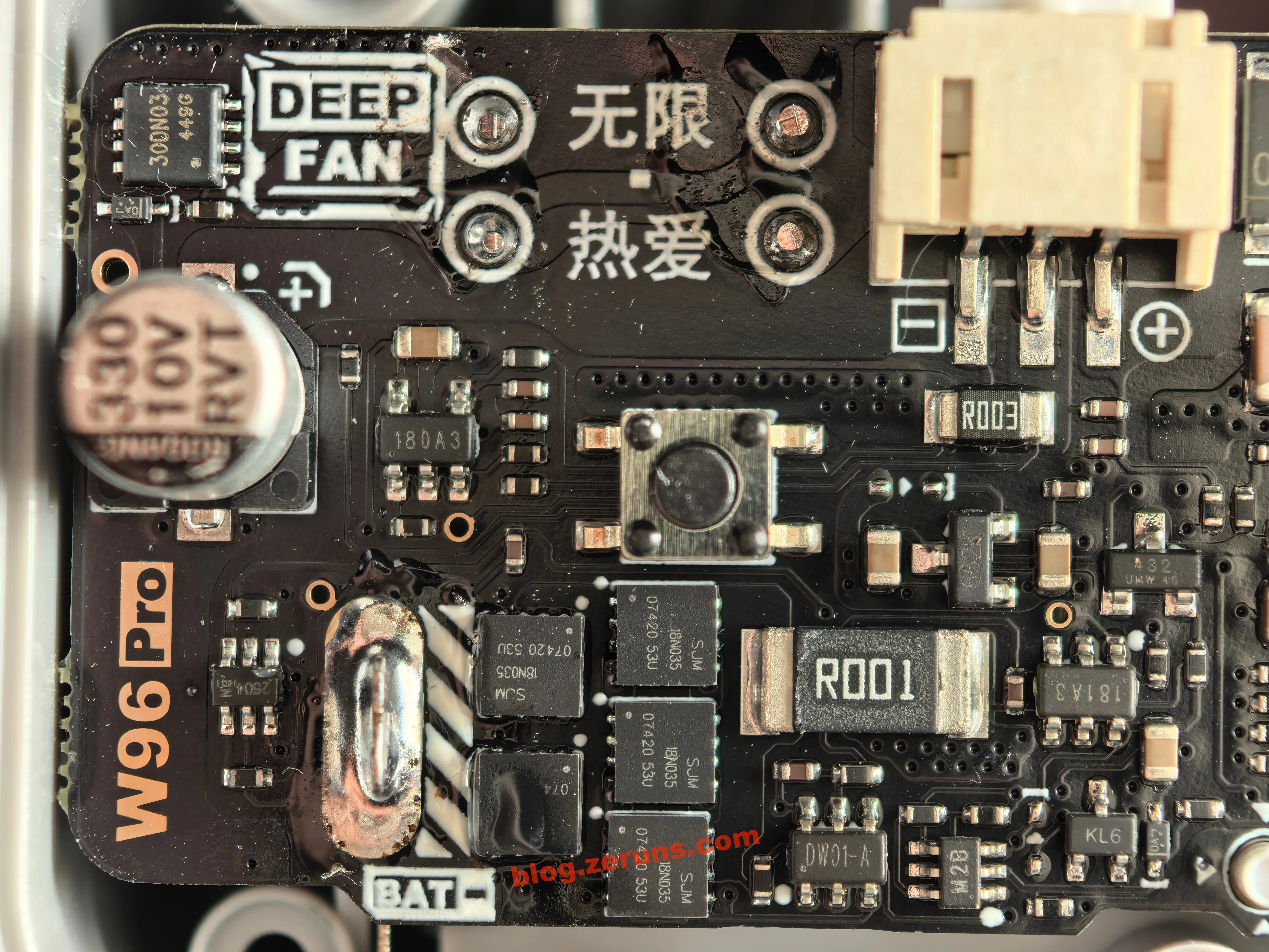
The circuitry at the motor connector and the battery negative terminal is shown in the photo below.
The ground lead of the motor interface goes through an R003 current-sense resistor (3mΩ), then through an op-amp marked 180A3 for amplification before reaching the MCU's ADC;
the battery negative passes through the protection circuit, then through an R001 current-sense resistor (1mΩ), amplified by the 181A3 op-amp and fed to the MCU's ADC. (The coulomb counter presumably works by integrating the current measured with this sense resistor, implemented in software on the MCU.)
INA180A3 — a 26V unidirectional current-sense amplifier from Texas Instruments (TI), SOT-23-5 package, fixed gain of 100 V/V.
- Common-mode input range: −0.2V ~ +26V (works for high-side or low-side sensing, independent of the supply)
- Bandwidth ~150kHz; offset voltage ≤±150µV; offset drift ≤1µV/°C; gain error ≤±1%
- Supply 2.7
5.5V; quiescent current ≤260µA; operating temperature −40+125℃INA181A3 — a 26V bidirectional current-sense amplifier from TI, SOT-23-6 package, fixed gain of 100 V/V, with a REF reference pin used to distinguish charge from discharge direction.
- Common-mode input range: −0.2V ~ +26V; bandwidth ~150kHz; offset voltage ≤±150µV; gain error ≤±1%
- Supply 2.7
5.5V; quiescent current ≤260µA; operating temperature −40+125℃- With the REF pin held at a reference potential, output above/below the reference corresponds to discharge/charge current respectively
Note: TI's official marking on these chips apparently isn't always the part number itself, so the two op-amps on this board may well be domestic (Chinese-made) substitutes.
To the upper right of the 181A3 is a voltage reference chip of the TL432 type, used to provide the voltage reference for the 181A3 — a stable "zero point" (the potential at the REF pin) so that bidirectional battery-current measurement can resolve charge versus discharge direction around it.
TL432 specifications (AI-generated):
- Core function: three-terminal adjustable precision shunt regulator (programmable Zener diode) — internal bandgap reference + error amplifier; the output voltage is set by two external resistors forming a divider, continuously adjustable from 2.5V ~ 36V
- Accuracy: graded into classes — commonly ±0.5% (B grade), ±1% (A grade), ±2% (standard grade)
- Output current: 1mA ~ 100mA (when used as a shunt regulator/reference source)
- Temperature coefficient: about 30ppm/°C (some vendors specify 50ppm/°C); low drift keeps the reference stable
- Dynamic impedance: typically around 0.2Ω
- Packages: SOT-23-3 / SOT-23-5 / TO-92, etc.; compatible parts include KA432, LM431, AS431, and others
- Role here: the TL432 outputs a stable voltage (for example, using two resistors to divide 3.3V down to a 1.65V midpoint) that connects to the INA181A3's REF pin, so the amplifier output parks at the midpoint when "zero current" flows — output above the reference means charging, below means discharging, letting the MCU's ADC read the current direction directly
At the top-left corner of the PCB there's an NMOS marked 300N03, apparently rated 30V/30A. My guess is it controls the supercapacitors' charge/discharge path, avoiding a momentary surge of current — and arcing sparks — when the battery is installed and instantly tries to charge them.
The lithium battery protection circuit is located to the right of the battery negative terminal, following the "DW01A protection IC + multiple high-current MOSFETs" approach.
DW01A specifications (AI-generated):
- Core function: single-cell Li-ion/Li-polymer battery protection IC; monitors battery voltage and CS-pin current, and drives external dual N-MOSFETs to cut off the charge/discharge paths
- Overcharge protection: 4.3V ±50mV (some vendors specify 4.28V), release voltage 4.1V, delay approx. 100ms
- Over-discharge protection: 2.4V ±75mV, release voltage 3.0V, delay approx. 50ms
- Overcurrent protection: CS-pin detection threshold 0.15V (in practice the sense point is usually placed across the FET itself, exploiting the voltage drop generated by its on-resistance); charge overcurrent at −0.15V, delay approx. 7~10ms
- Short-circuit protection: threshold approx. 1.0
1.35V, delay of only 300600µs- 0V battery charging: supported (deeply over-discharged cells can be activated)
- Quiescent current: approx. 3~6µA; approx. 0.7µA in low-power mode
- Package: SOT-23-6 (SOP-8 and other variants exist), with numerous domestic equivalents (Fuman, Changxin, etc.)
SJM 18N035 specifications (AI-generated):
- Type: N-channel enhancement-mode power MOSFET
- Voltage rating: VDS ≈ 30V
- Current rating: ID ≈ 18A
To the left of the battery negative terminal there's also a 6-pin chip marked 2604 — I couldn't find any documentation and don't know exactly what it does, though it's presumably related to battery protection as well. The Gongtian F95D mini fan I tore down last time had this same chip too.
To the right of the DW01A is yet another 6-pin chip marked M2B; I couldn't find documentation for it either, nor determine its purpose.
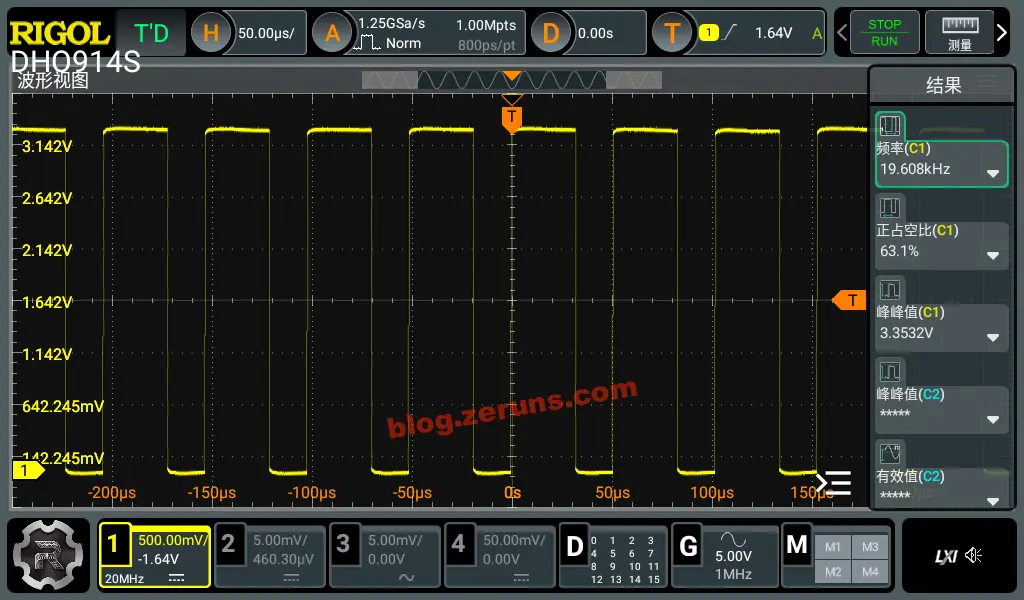
Motor Control Waveforms at Different Levels
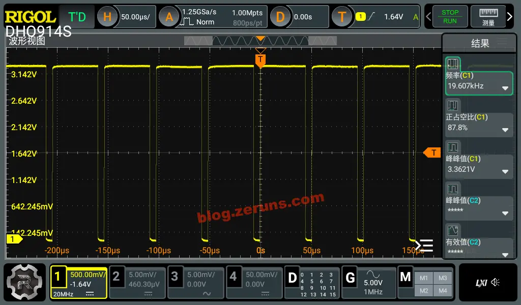
Using my DHO914S oscilloscope I probed the waveform on the motor's PWM control pin. At 25% wind speed, the measured PWM frequency was 19.6kHz with a duty cycle of 63.1%.
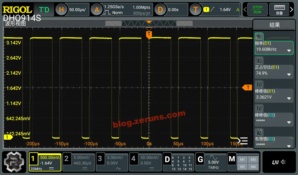
At 50% wind speed, PWM frequency 19.6kHz, duty cycle 74.9%.
At 75% wind speed, PWM frequency 19.6kHz, duty cycle 87.8%.
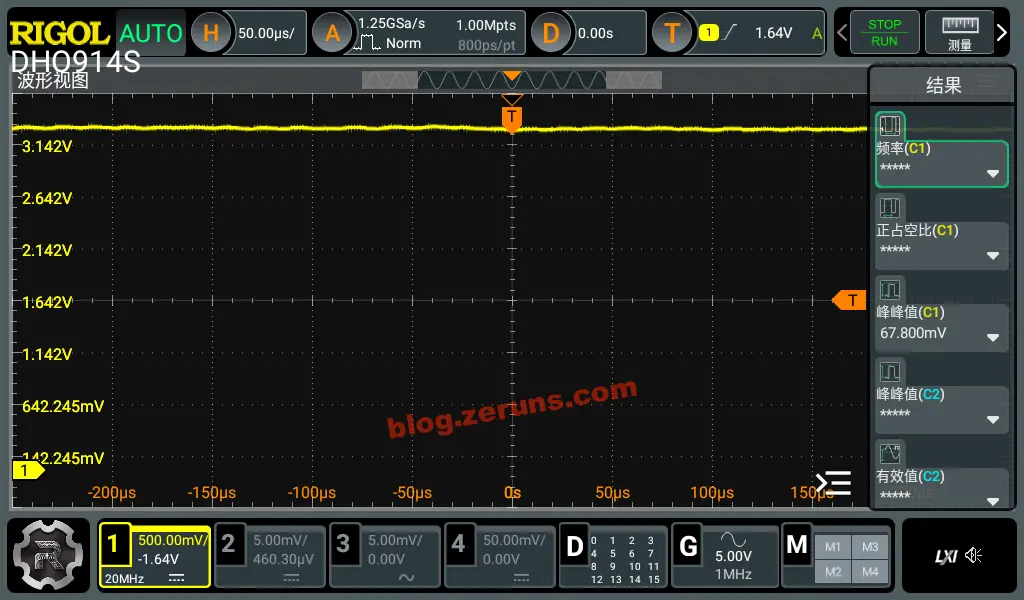
At 100% wind speed, the duty cycle is 100% — i.e., fully on continuously.
Summary
- Good component quality, with generous design margins.
- The companion mini program is feature-rich, and shows quite a lot of data.
- 18W charging is nice, and the fan doubles as a charger for other devices.
- Airflow and air volume are good; the top level is rather loud, while 35% offers a good balance between airflow and noise.
- At maximum speed the airflow is strong enough that the fan can't stand upright and will tip over.
- Runtime is roughly 8 hours at 35%; respectable.
Recommended Reading
- Cost-effective and budget-friendly VPS/cloud server recommendations: https://blog.zeruns.com/archives/383.html
- Overview and recommendations for major AI LLM API platforms: https://blog.zeruns.com/archives/947.html
- Minecraft server hosting tutorials: https://blog.zeruns.com/tag/mc/
- Complete guide to deploying a Hermes Agent — build your first AI assistant step by step: https://blog.zeruns.com/archives/939.html
- Ugreen DXP4800Pro NAS unboxing, review and teardown: https://blog.zeruns.com/archives/949.html
- MQTT explained in one article — how the "post office" of the IoT world works: https://blog.zeruns.com/archives/951.html
评论