


A simple unboxing, review, and teardown of the GL-RM1PE and the FGB-01 Finger Robot, enabling BMC-style remote management on a regular PC.
Review video: https://www.bilibili.com/video/BV1kBnNzsEBq/
GL-RM1PE Overview
The GL-RM1 is a widely used remote KVM device (IP-KVM) launched by GL.iNet. With this device, you can remotely control your home computer, access local resources, or transfer files while away. Its features also include controlling offline devices, troubleshooting boot failures, and adjusting BIOS settings. The added audio support provides a more immersive remote interaction experience. As a versatile tool for both remote work and IT management, the GL-RM1 greatly improves operational efficiency.
The GL-RM1PE is the PoE version of the GL-RM1, designed to simplify single-cable setups. It provides both power and network connectivity through a single Ethernet cable, reducing cable clutter and simplifying installation. This version also upgrades the onboard eMMC storage to 32GB, enhancing its ability to handle system logs, recordings, and custom firmware.
- GL-RM1PE User Guide: https://docs.gl-inet.cn/kvm/user_guide/gl-rm1pe/
- GL-RM1PE Purchase Link: https://s.click.taobao.com/yyVXdXq
FGB-01 Finger Robot Overview
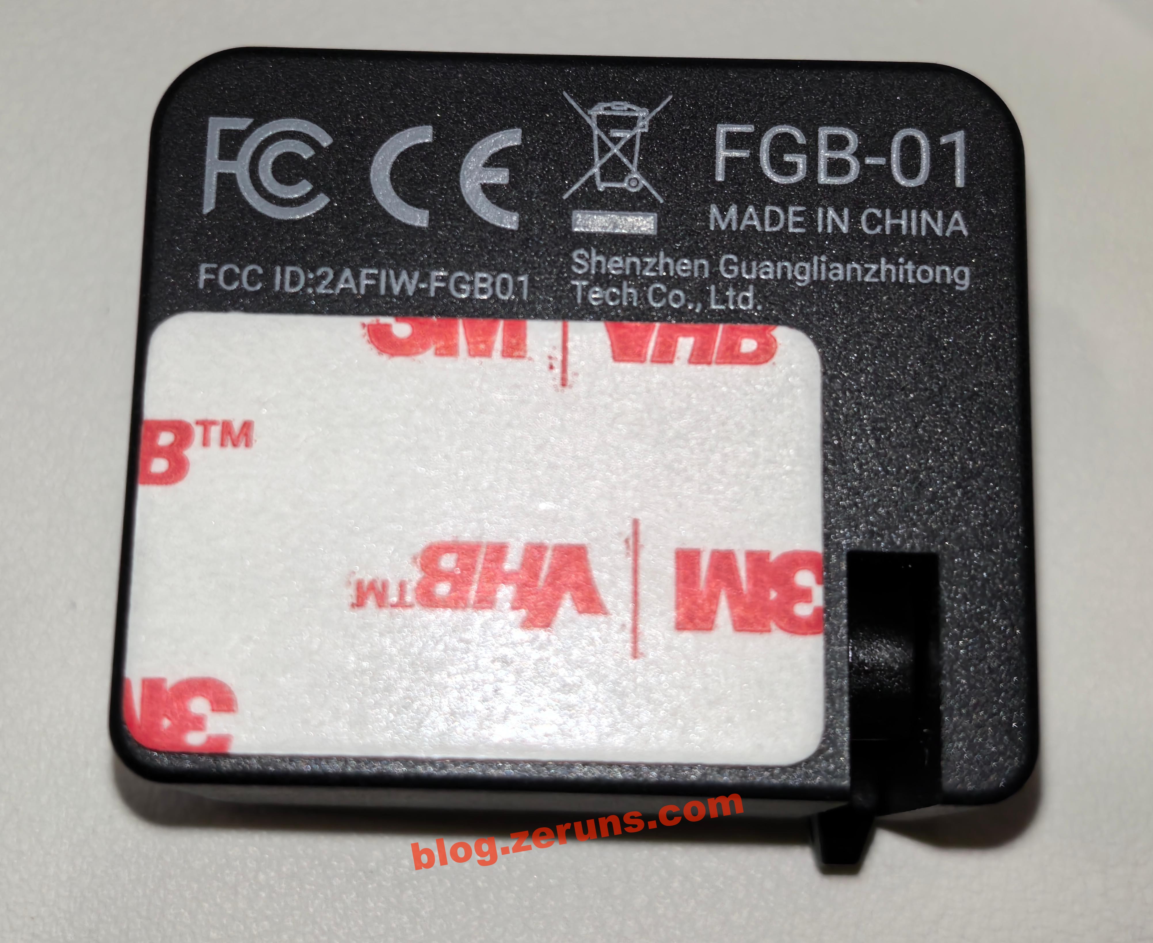
The FGB-01 is an optional accessory provided by GL.iNet for KVM devices, offering extra convenience for remote management.
The Finger Robot acts as a physical button emulator, designed to remotely control the power button of the target device. As a button simulator, it is specifically designed for remote PC power on/off control. It is easy to install with adhesive mounting, features a battery life of up to one year, and requires no complicated setup, making it suitable for everyday use.
Alternatively, users may choose the GL-ATX board, which can be installed inside the chassis and connected directly to the power switch pins (F_PANEL), enabling direct control over power operations.
Use Cases
- Server Room Centralized Management: Simplified wiring with single-cable PoE, remote video monitoring of servers, system power control, and fault intervention.
- Enterprise Remote Maintenance: Hardware-level remote control without requiring the target device to be online or booted, quickly resolving BSODs, boot failures, and reducing on-site inspection costs.
- Remote System Installation & Maintenance: Mount ISO images as virtual CD-ROM/USB drives to perform OS installation, reinstallation, and firmware upgrades remotely, supporting bulk deployment.
- Unattended Device Control: PoE adaptation for outdoor/industrial environments, paired with accessories for remote power control, real-time monitoring, and low-maintenance management.
Specifications
| Feature | GL-RM1PE | GL-RM1 | Others |
|---|---|---|---|
| Latency | ~30–60ms | ~30–60ms | >100ms |
| Ethernet Speed | 1Gbps | 1Gbps | 100Mbps |
| Power Supply | PoE/DC | DC | DC |
| Resolution | 3840x2160@30FPS | 3840x2160@30FPS | 1920x1200@60FPS |
| BIOS-level Access | Supported | Supported | Supported |
| macOS/Windows App Support | Supported | Supported | Not Supported |
| Remote Audio | Two-way | One-way | None |
| Remote File Transfer | Supported | Supported | Not Supported |
| File Transfer Speed | 25MB/s | 10MB/s | Not Supported |
| Remote System Installation | Supported | Supported | Supported |
| Storage Space | 32GB eMMC | 8GB eMMC | 128MB |
| Casing | Aluminum Alloy | CNC Metal | PVC Plastic |
Unboxing
GL-RM1PE
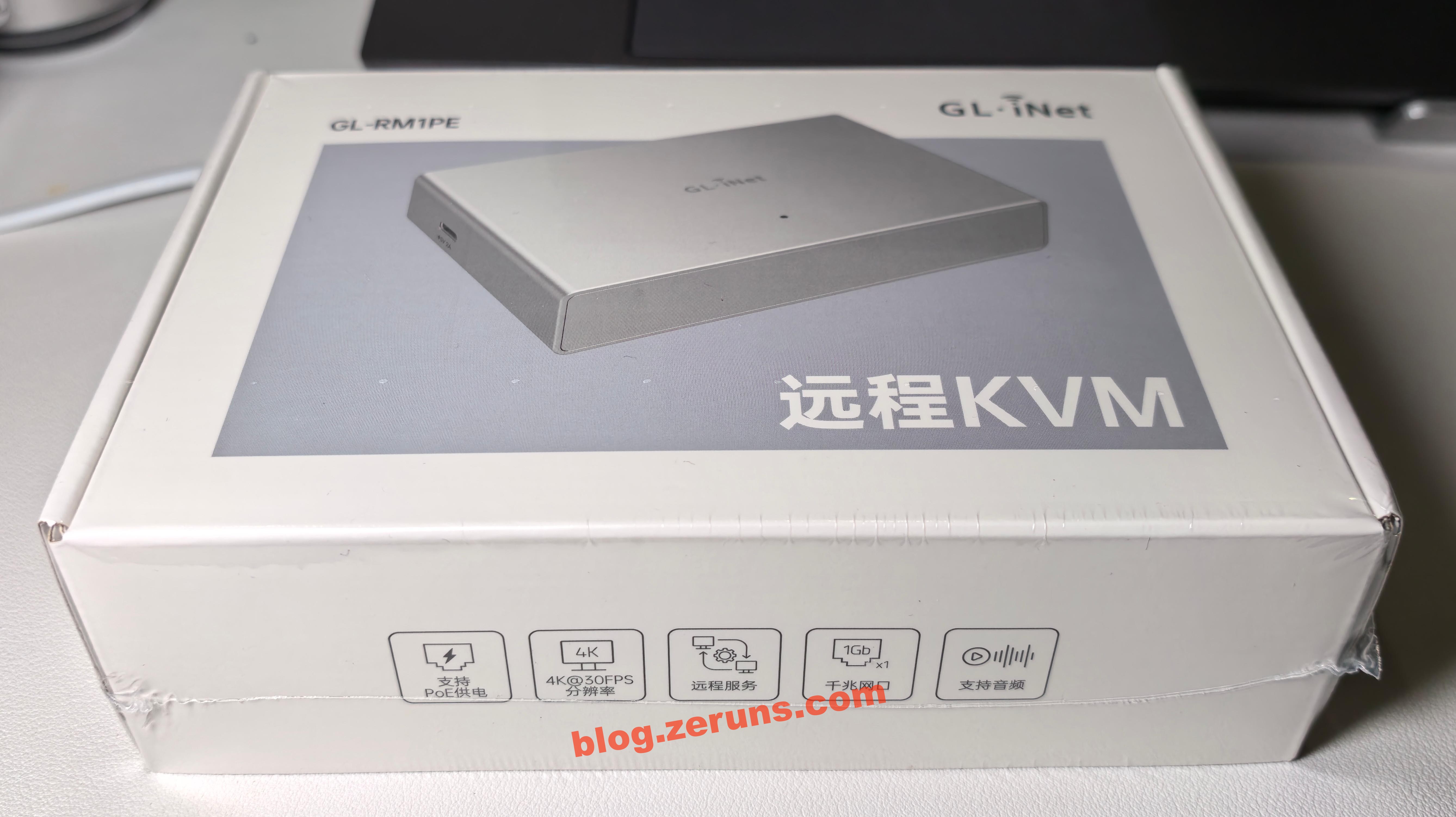
Front of the box
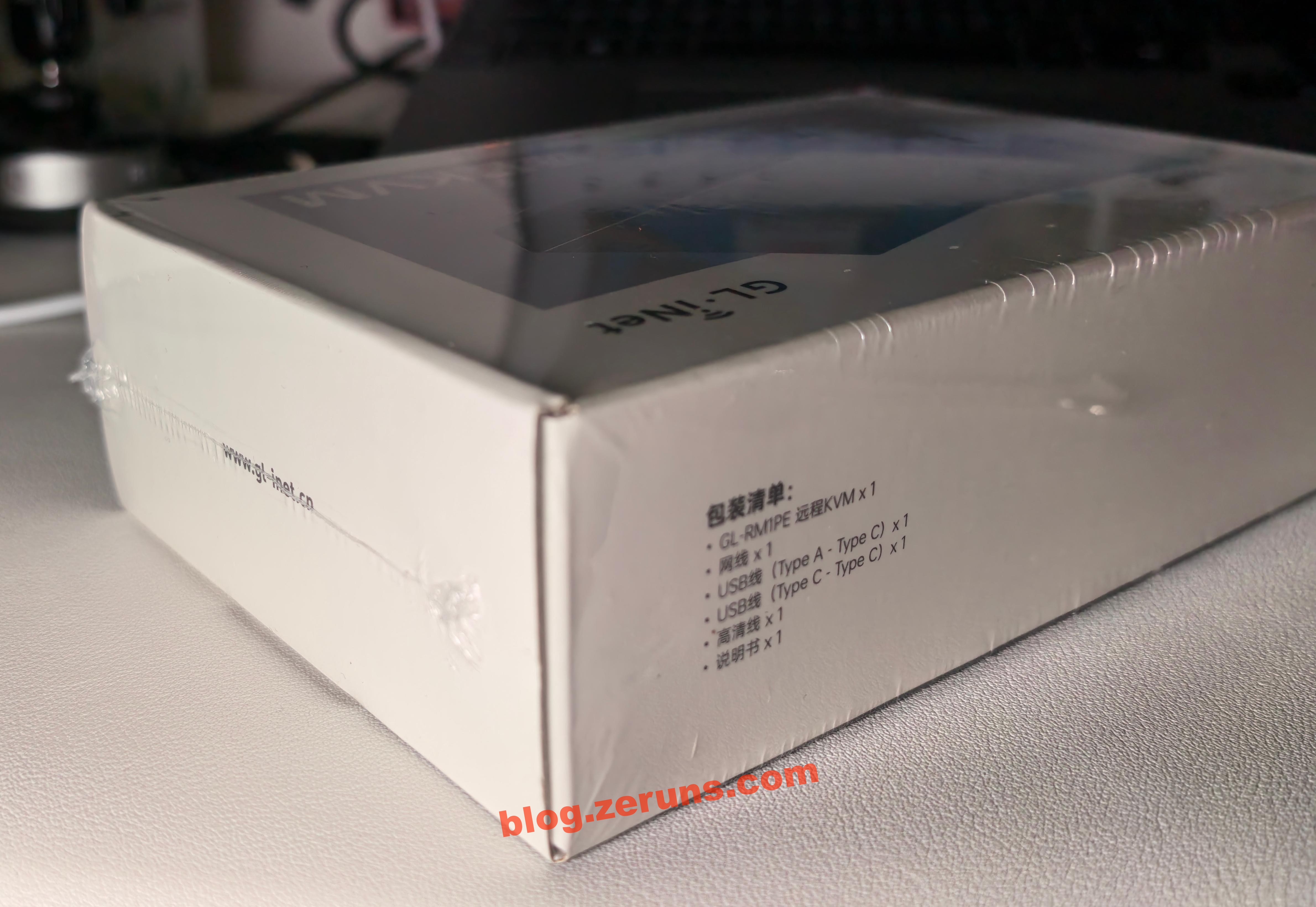
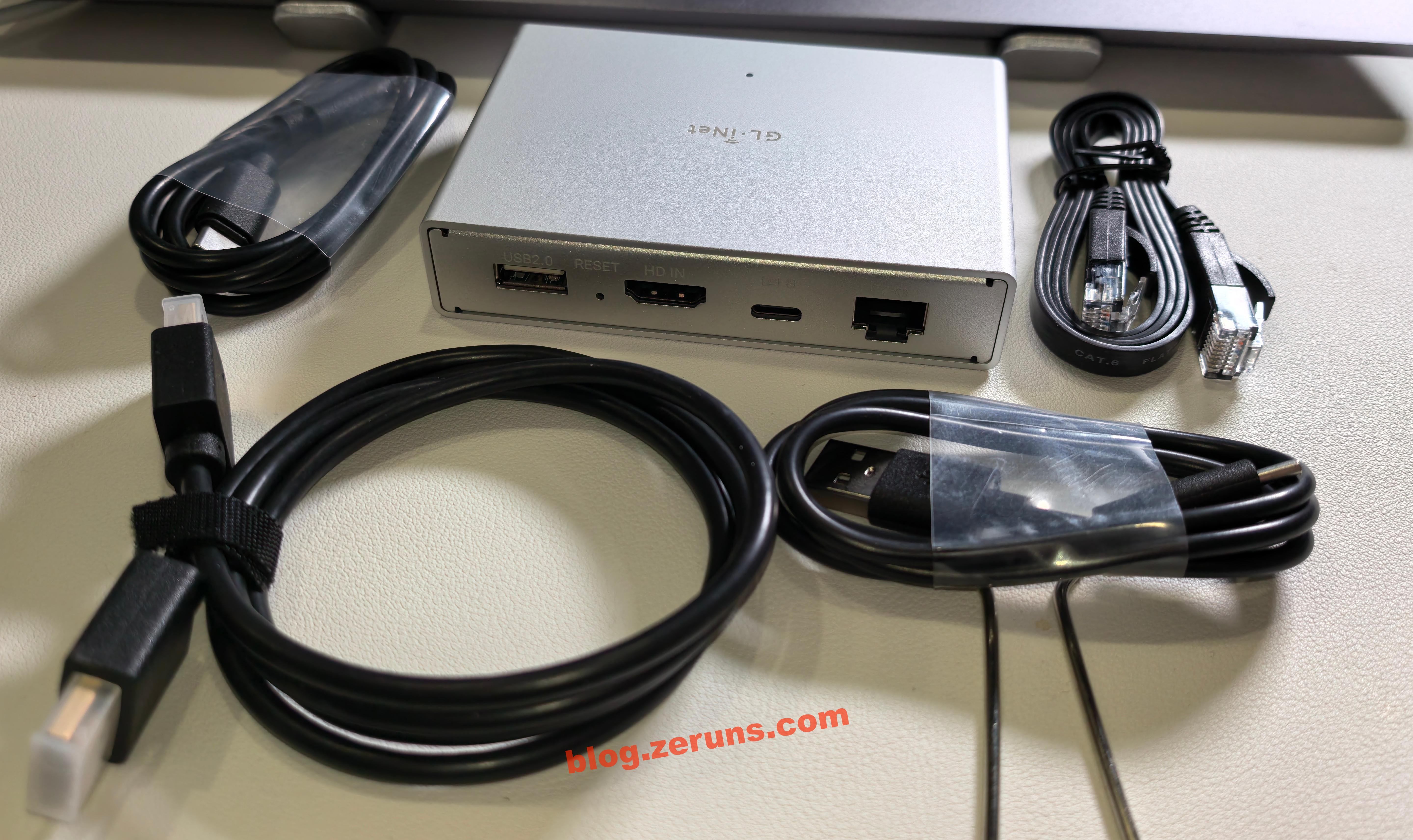
Side of the box, showing the company website and the package contents:
- GL-RM1PE Remote KVM
- Ethernet cable
- USB cable (Type A – Type C)
- USB cable (Type C – Type C)
- HDMI cable
- User manual
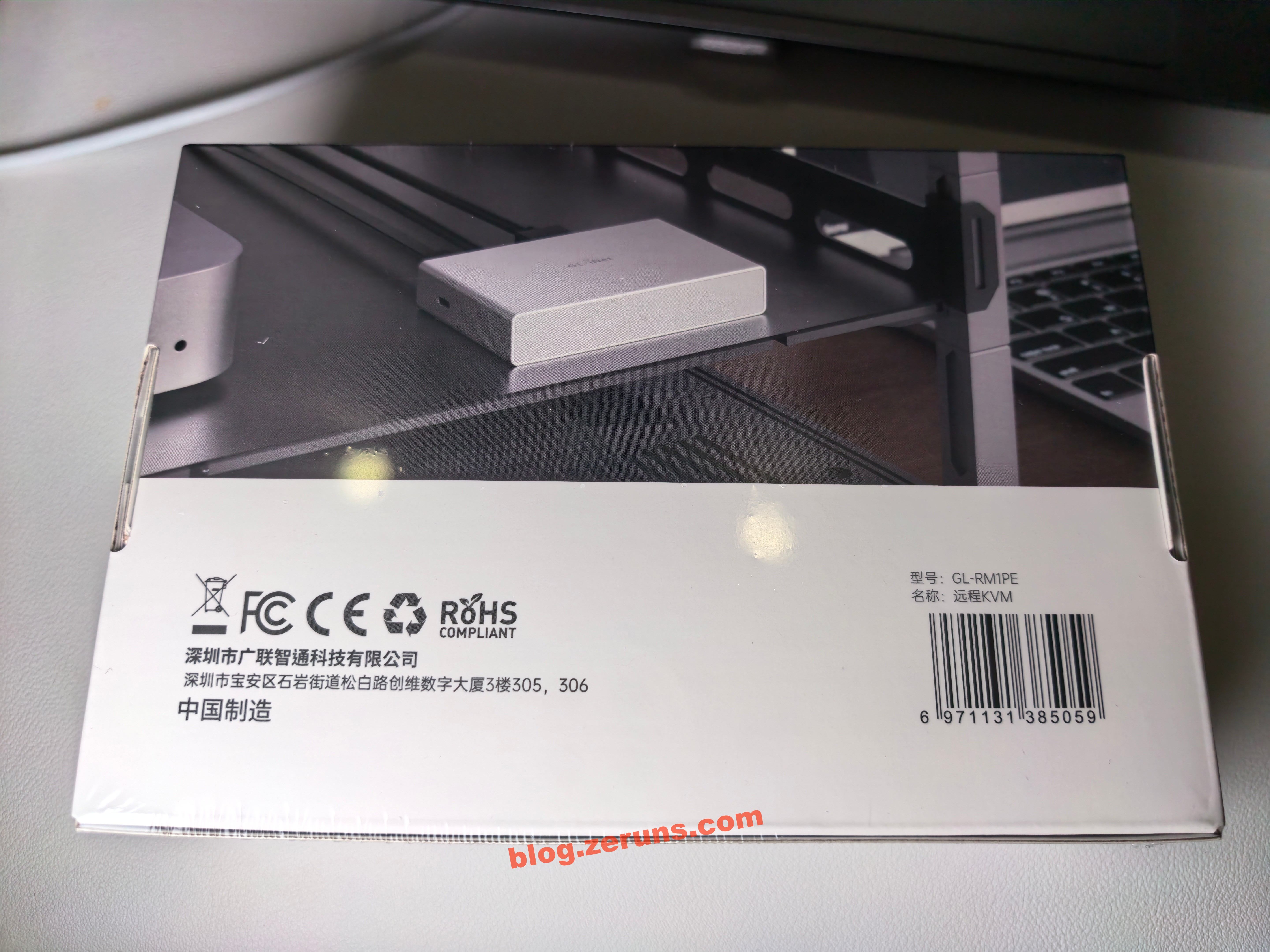
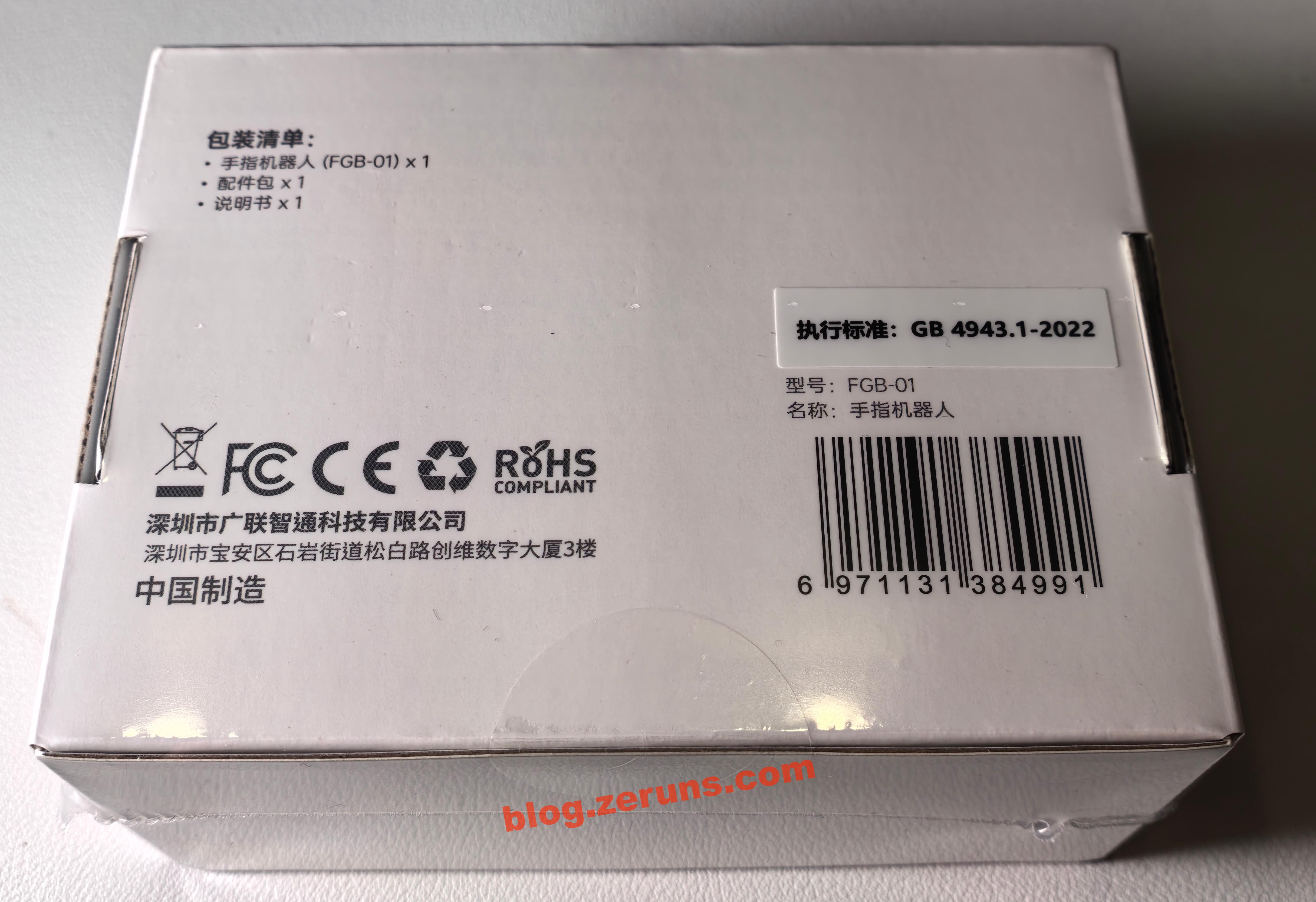
Bottom of the box, showing the company name and address
Opening the box reveals the manual and the device on top, with accessories and cables underneath
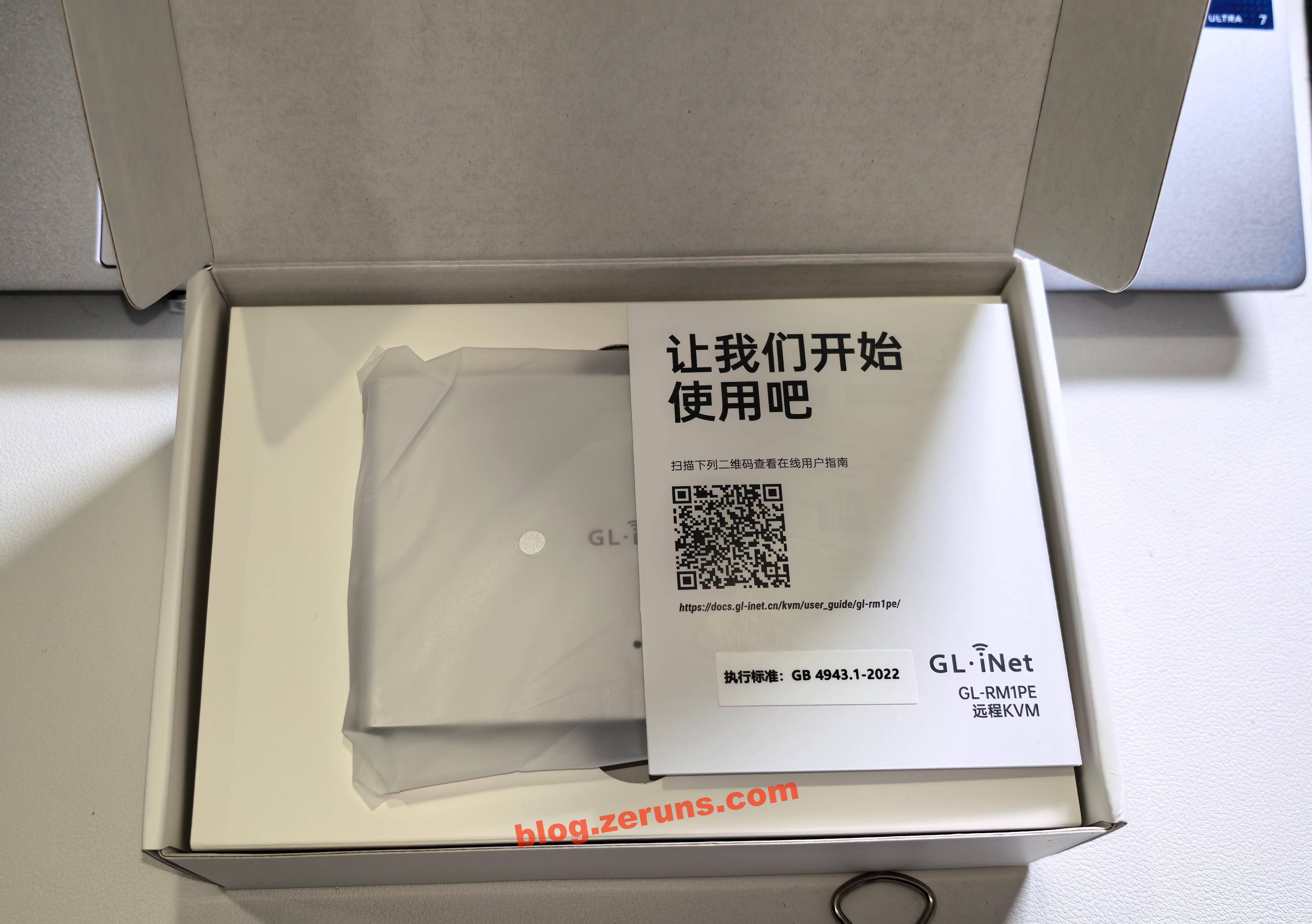
GL-RM1PE manual
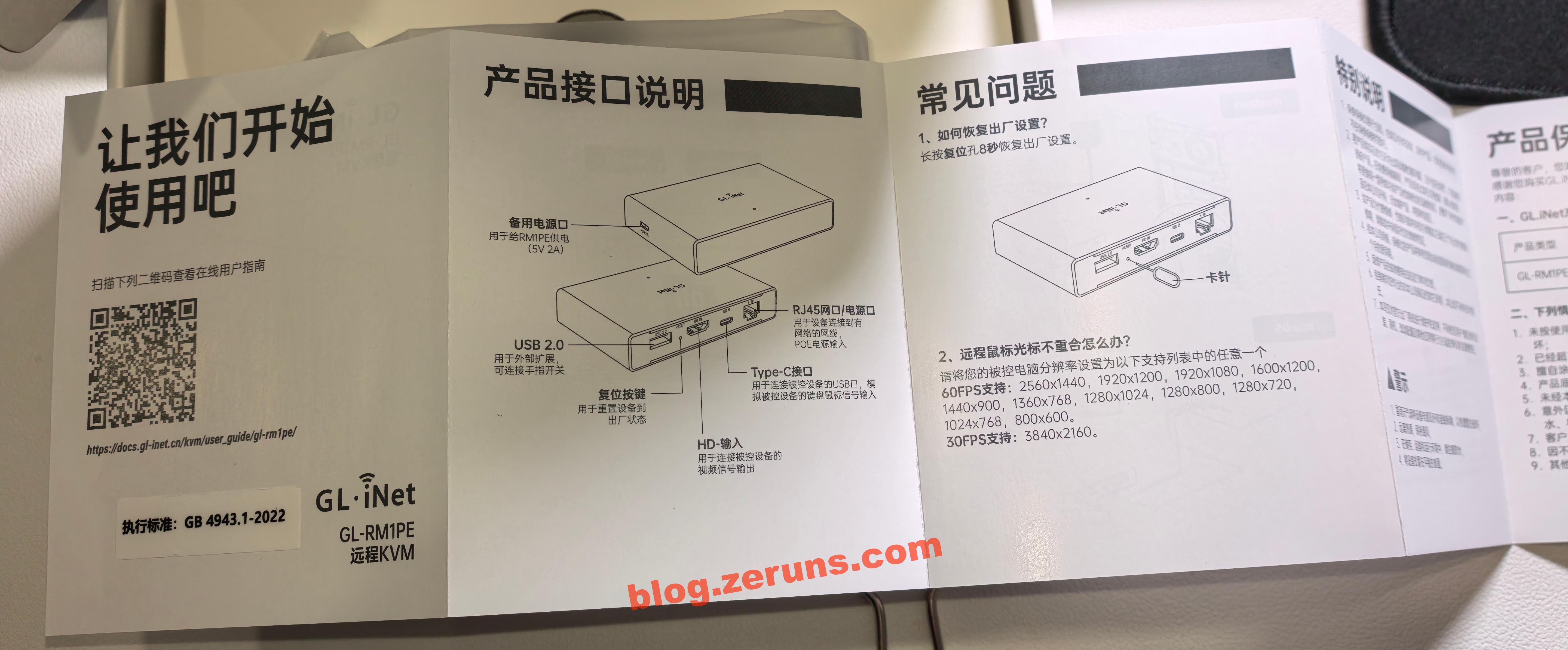
The GL-RM1PE with included cables. On the back, the ports include USB-A (for connecting the GL-ATX board or Finger Robot), HDMI (for capturing the target system’s video signal), Type-C (for keyboard and mouse emulation), and an RJ45 Ethernet port (PoE supported). On the side, there is a Type-C power port (5V, PD compatible).
FGB-01 Finger Robot Unboxing
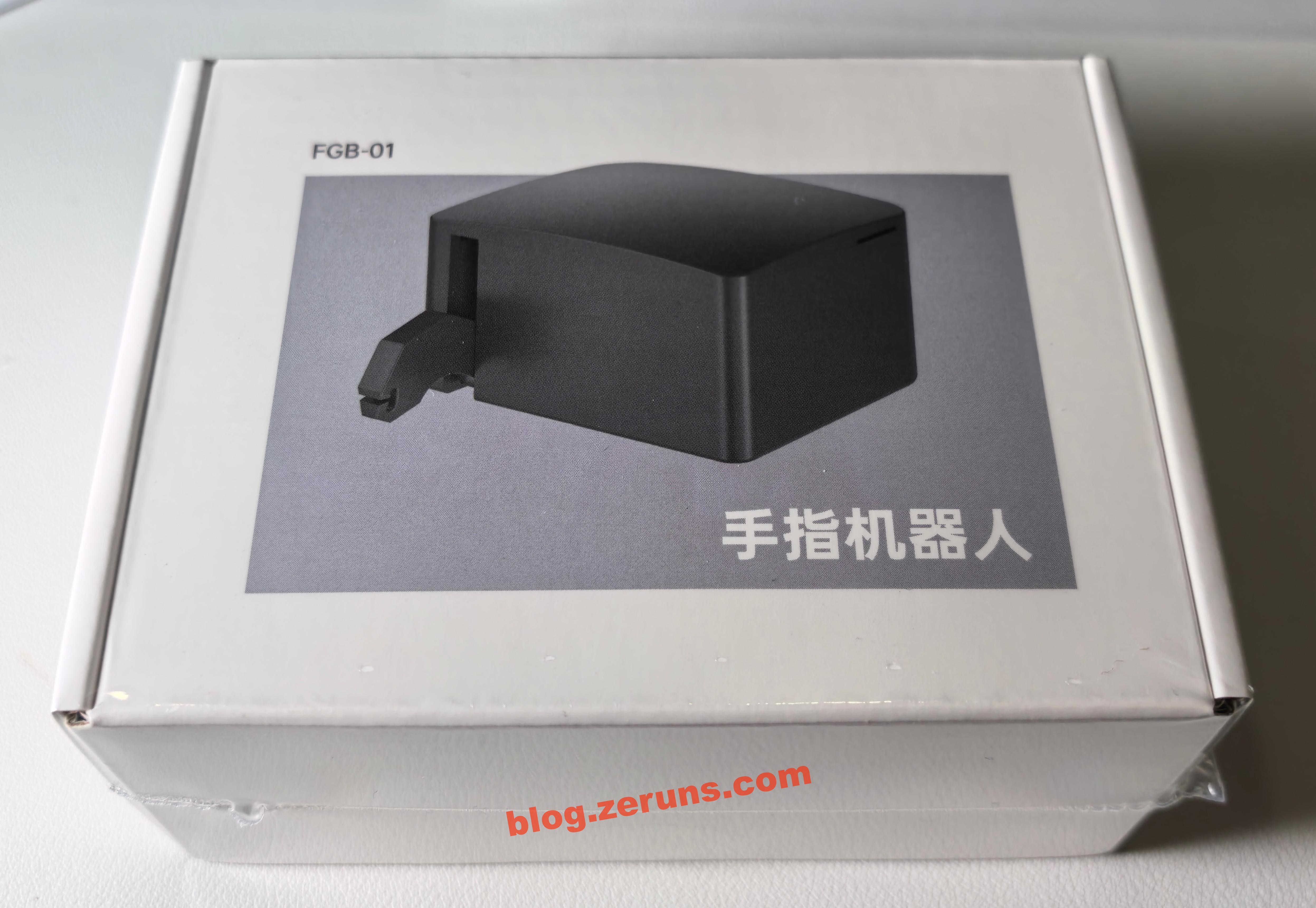
Front of the box
Bottom of the box, listing the company name and package contents:
- Finger Robot (FGB-01)
- Accessory pack
- User manual
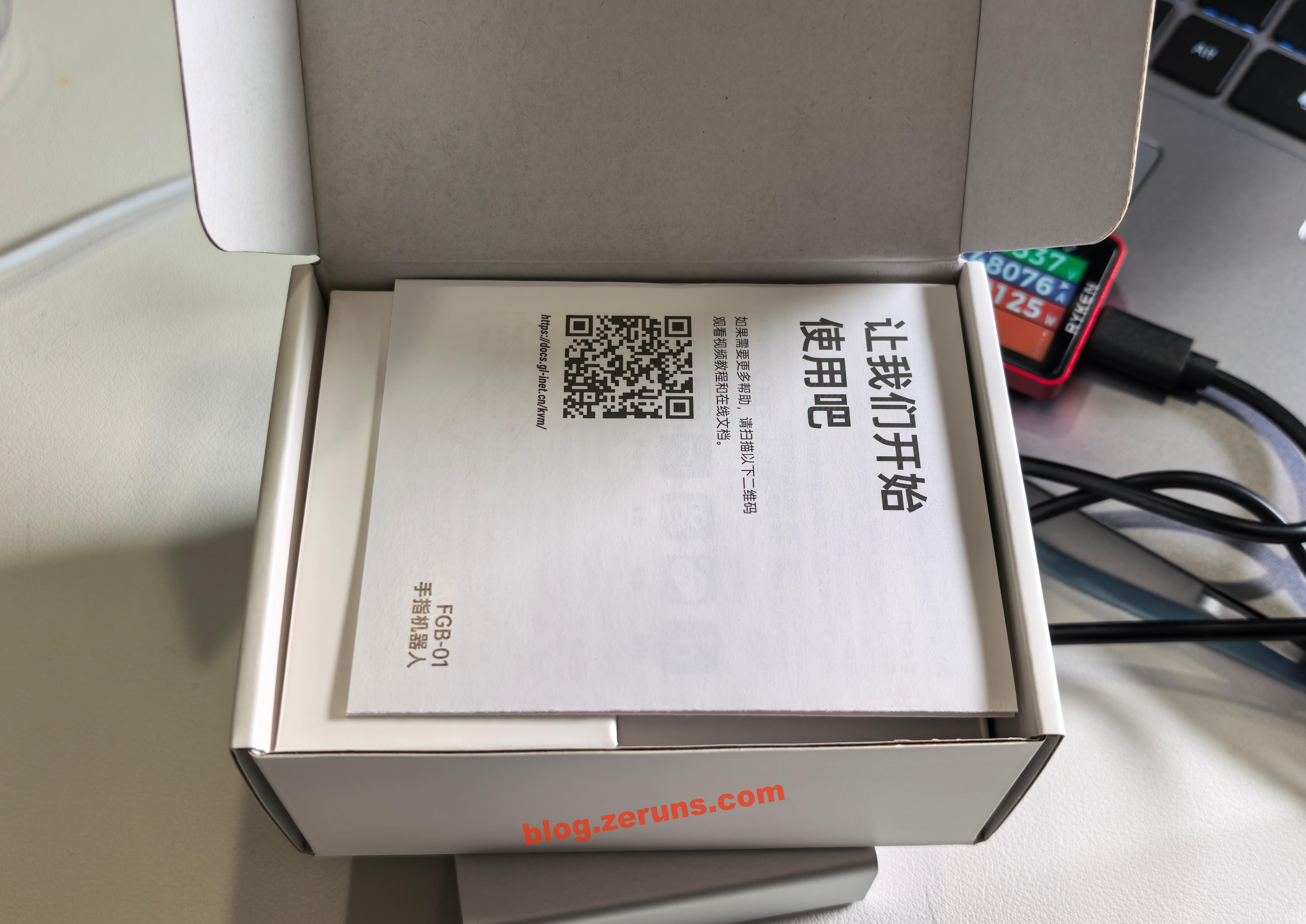
Opening the box, the manual is on top
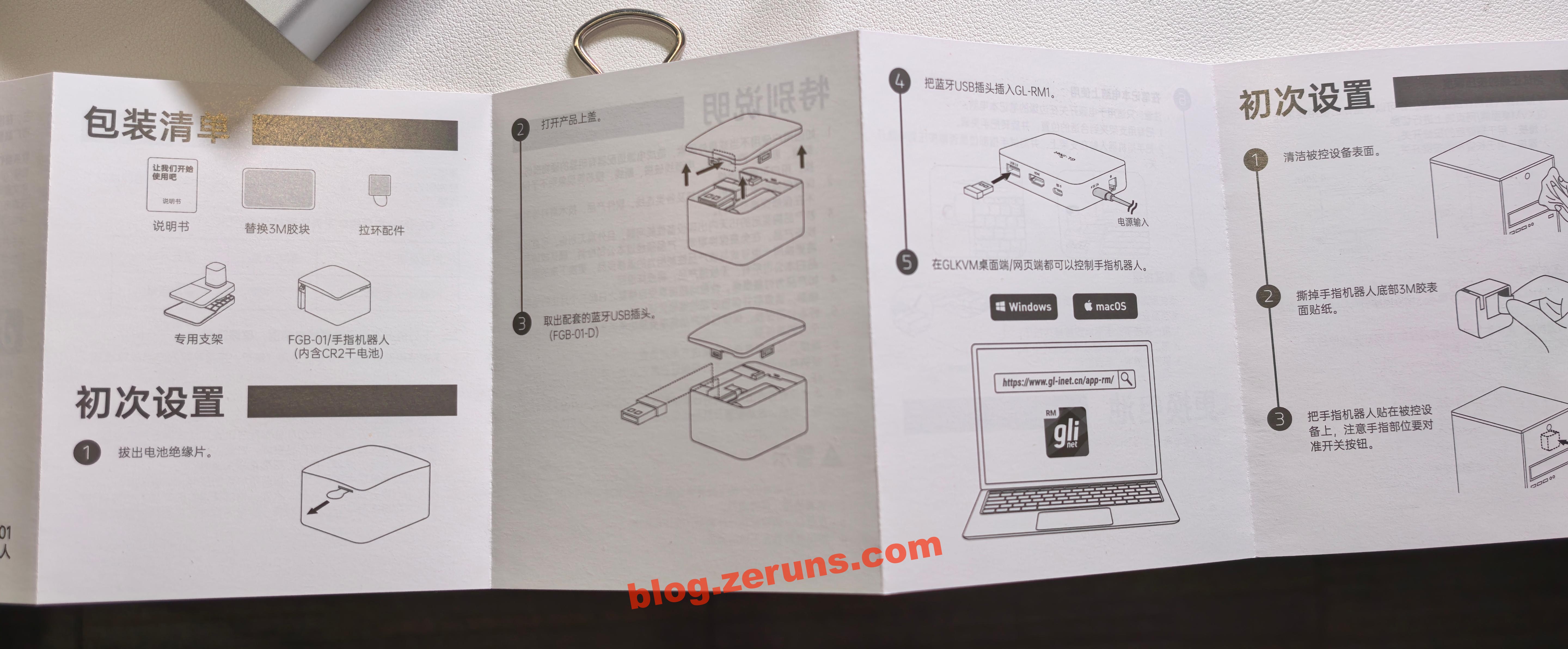
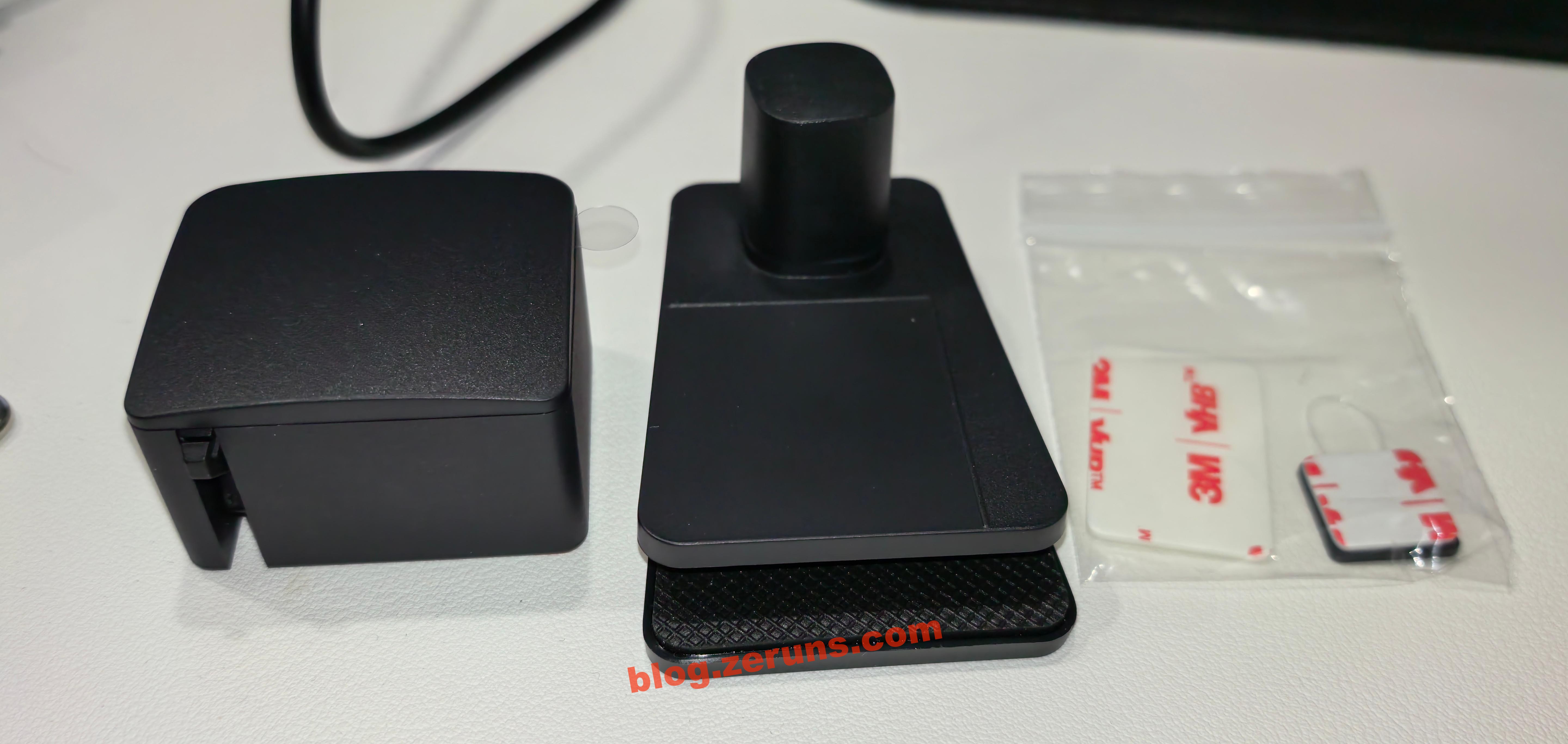
Next are the Finger Robot unit and accessories
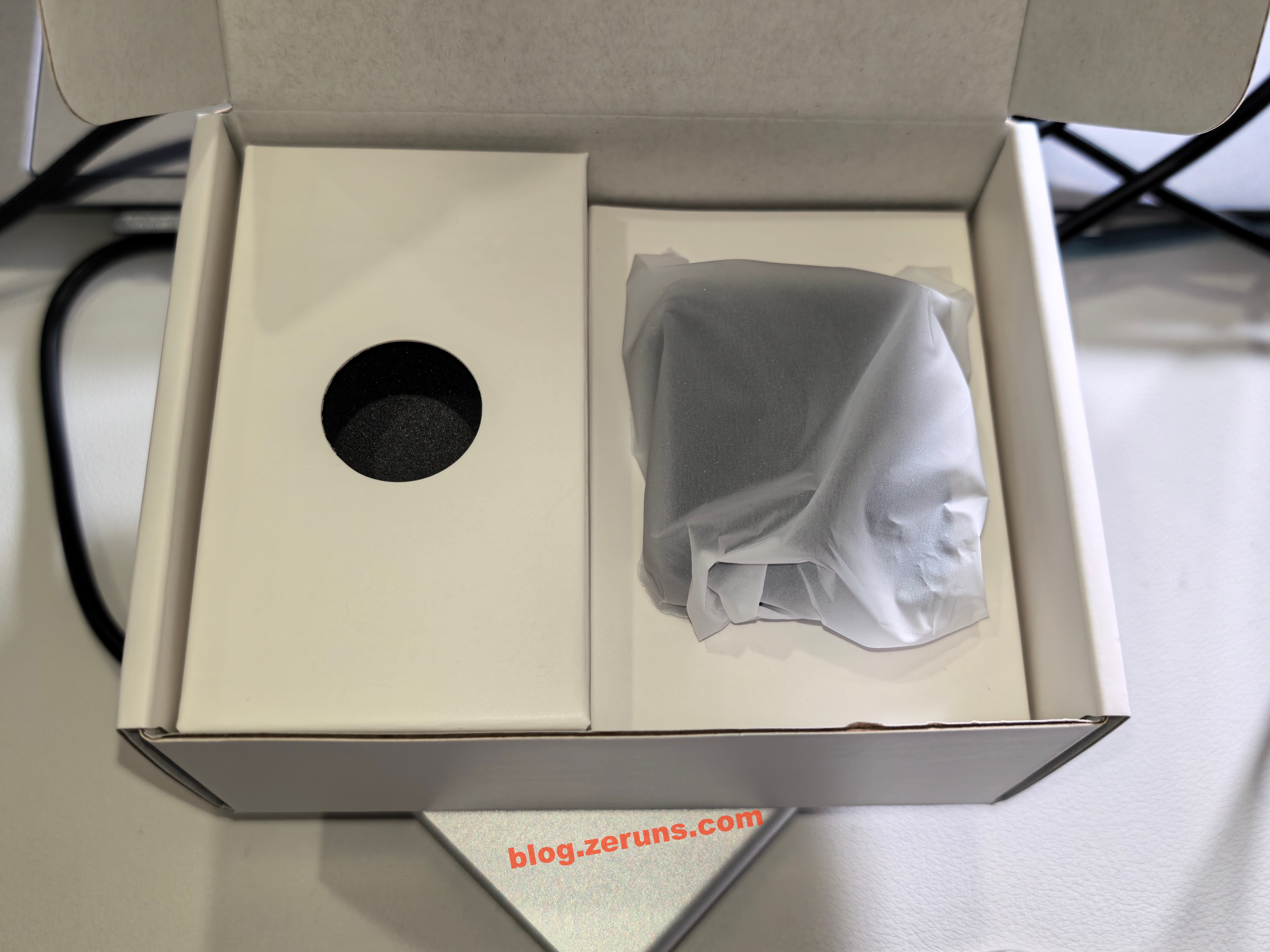
Accessories include two 3M double-sided adhesive pads and a clip (used for attaching the Finger Robot securely to a laptop).
Review & Usage Guide
GL-RM1PE
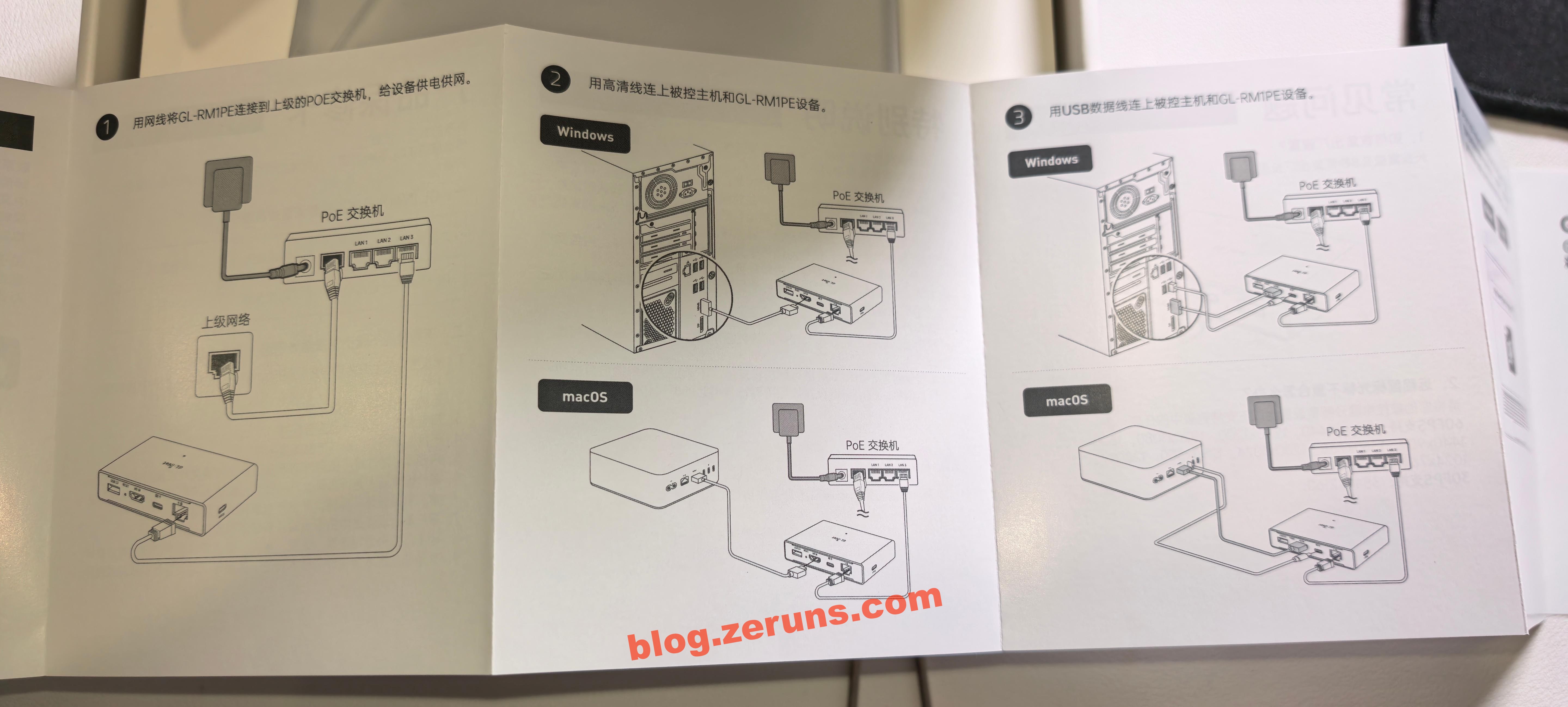
First, connect the GL-RM1PE to the target computer using the HDMI and Type-C (the one next to HDMI) ports, then connect the Ethernet and power cable (side Type-C port).
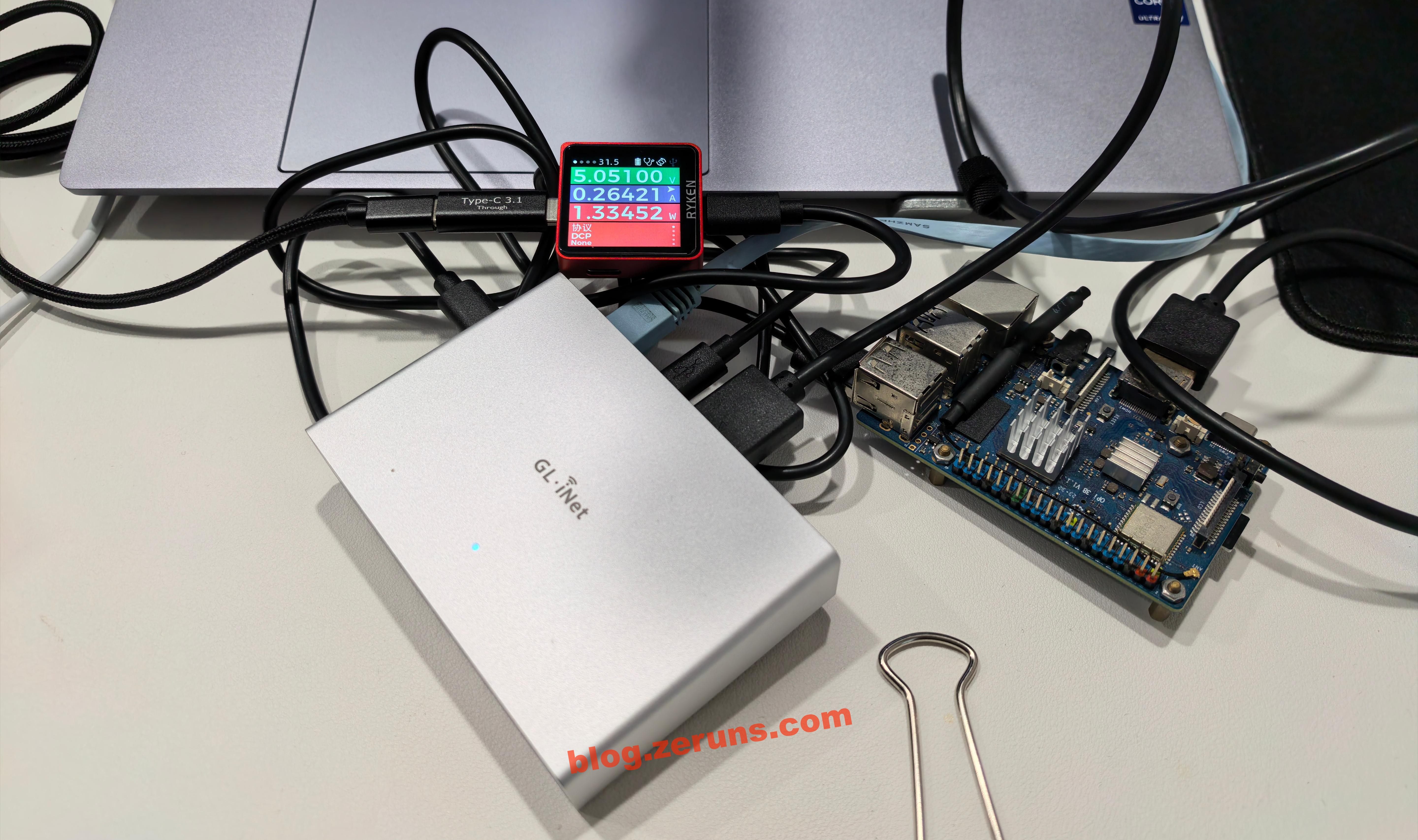
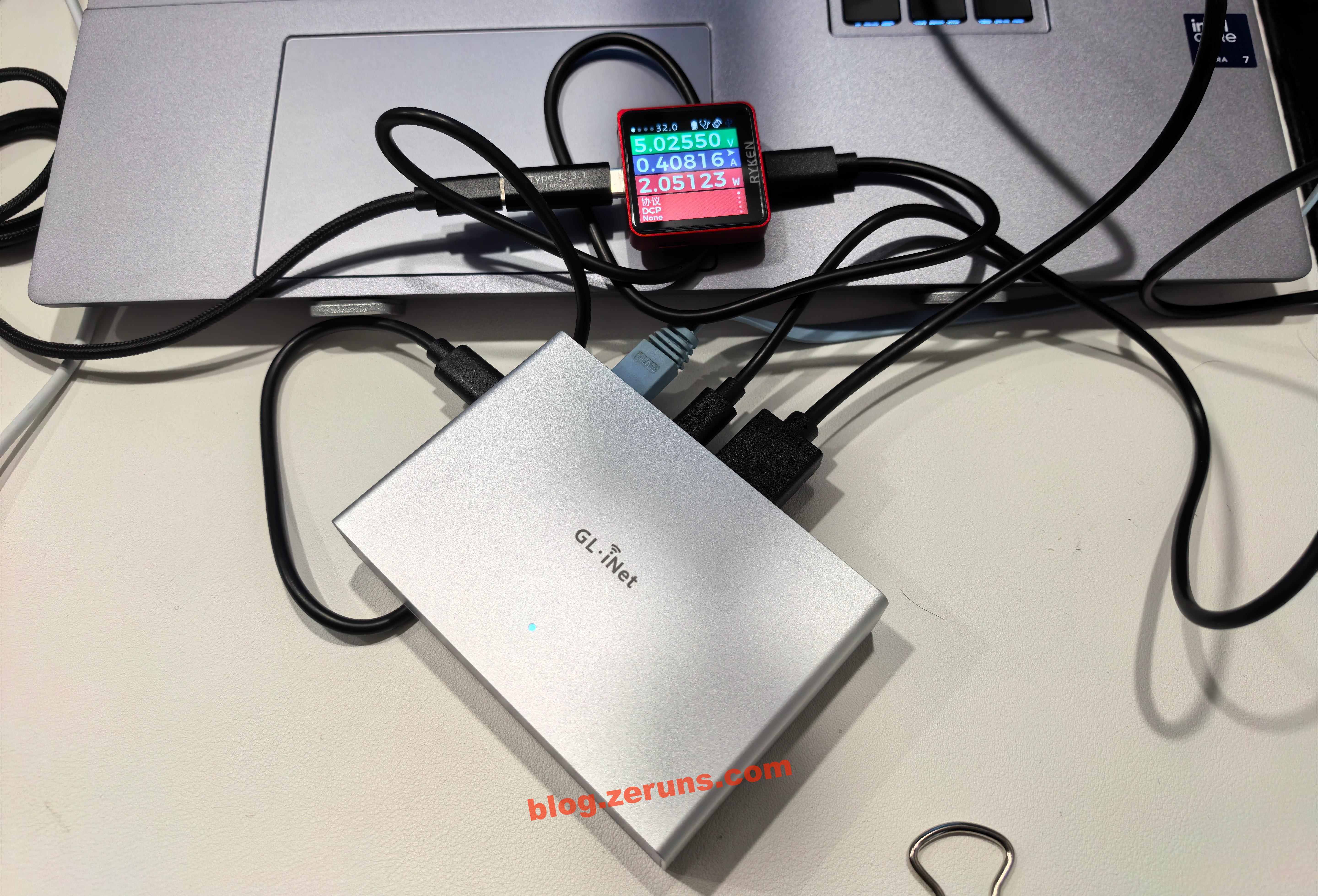
Wait until the indicator light turns solid white, which means the device has finished booting. Once running, the GL-RM1PE consumes about 2W of power.
USB power meter: https://s.click.taobao.com/bQtCNLq
After booting, find the device’s IP address in the router’s management page and enter it in a browser to open the control panel. On the first login, you must set a password. Alternatively, you can download the client from GL.iNet’s official website to search for and bind the device (must be on the same LAN). If outside the LAN, you can bind it using the device’s SN serial number. Once bound, you can use the client to control remotely even across networks. Tailscale (built-in client) can also be used to create a virtual LAN for remote access.
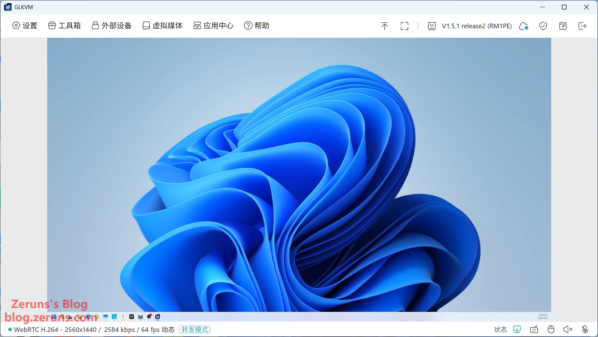
The video stream is smooth; refer to the review video link above for detailed results.
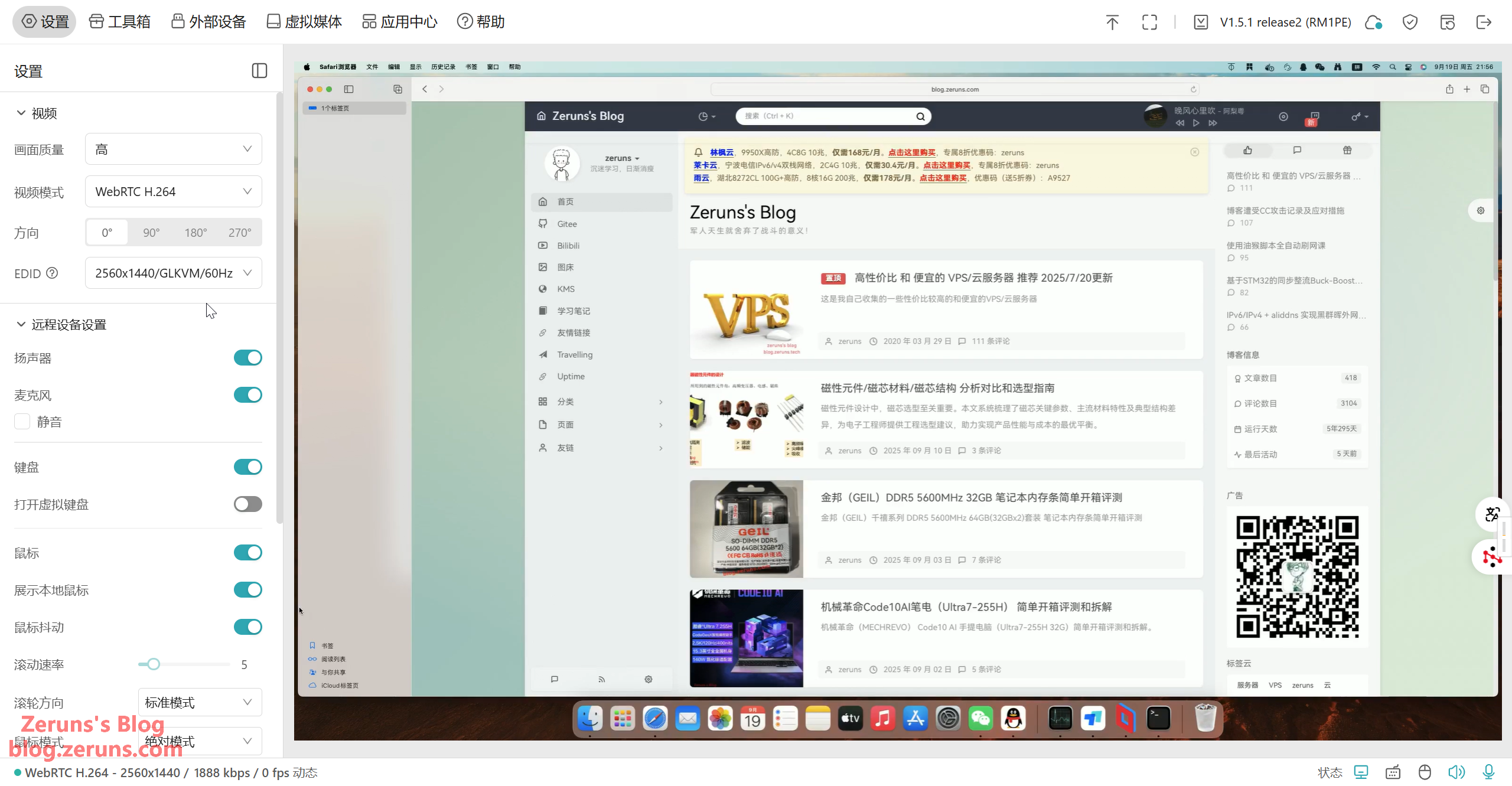
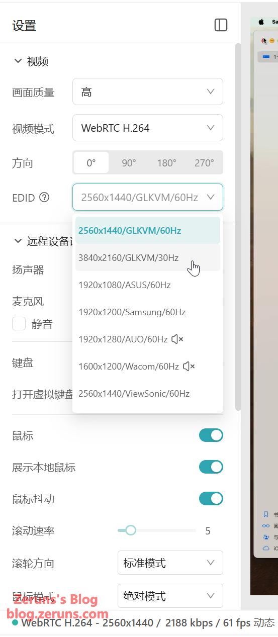
You can edit HDMI EDID information. Maximum supported resolution is 4K@30fps. Video encoding supports only H.264.
You can transmit the local microphone’s audio to the target device (recognized as a USB microphone) and also stream the target device’s speaker output. It also supports a virtual keyboard.
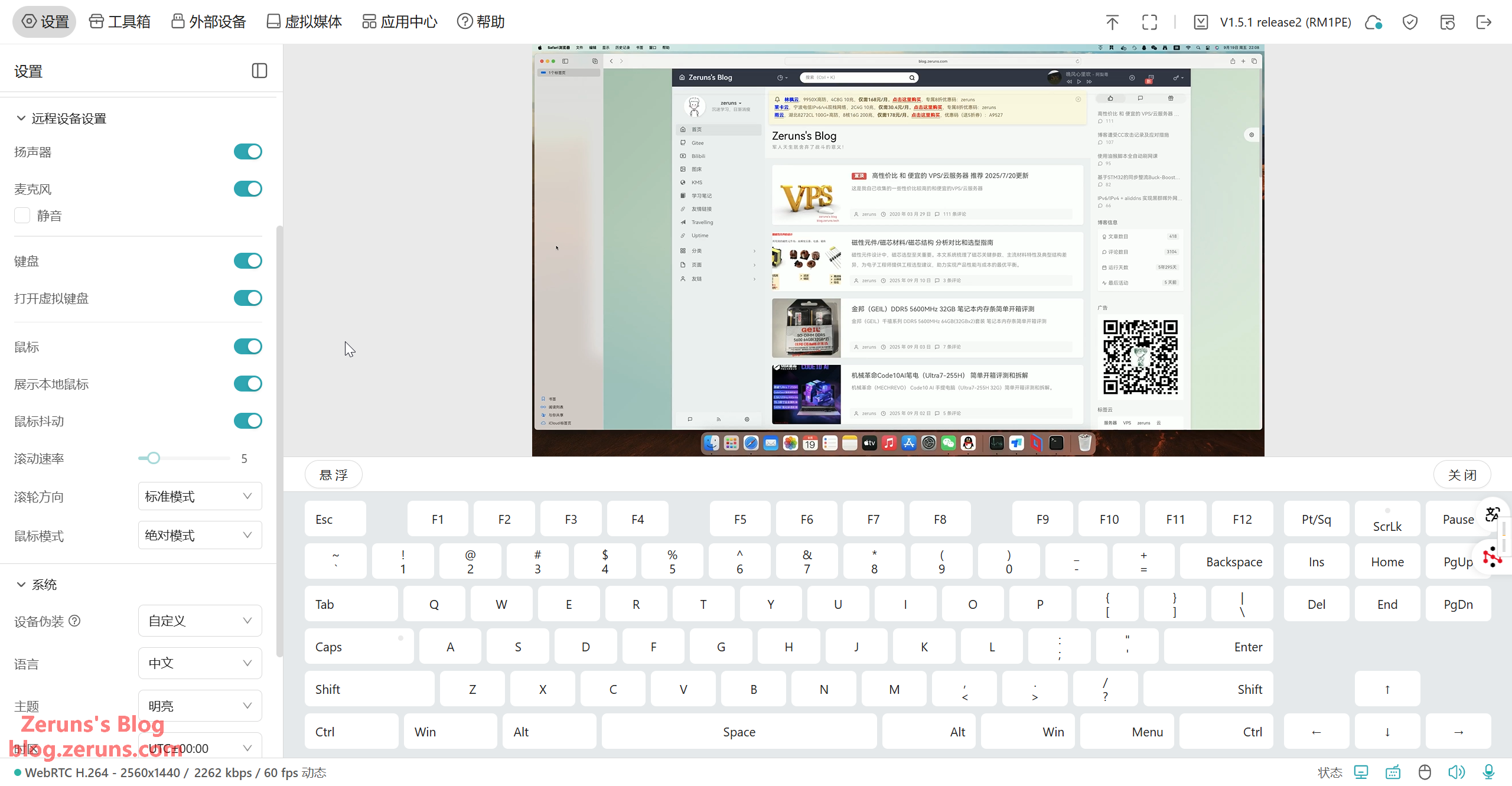
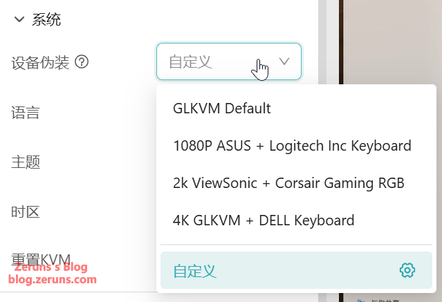
Device emulation is supported.
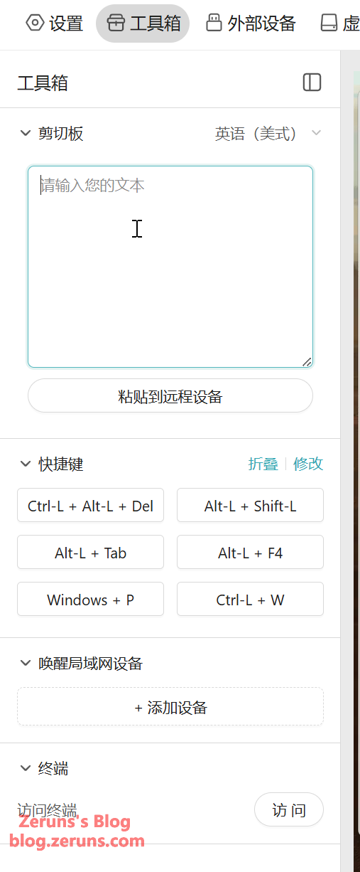
The toolbox allows you to copy/paste text to the remote device, use quick shortcuts, and wake devices on the LAN.
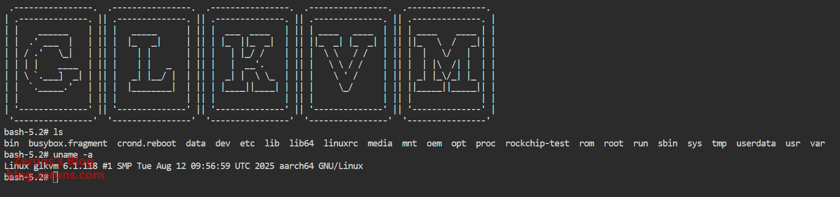
The terminal feature gives access to the GLKVM system shell, showing that GL-RM1PE runs a Linux 6.1 kernel.
When connected to the Finger Robot or GL-ATX board, you can control the power button of the target device under “External Devices.” The press duration can also be customized.

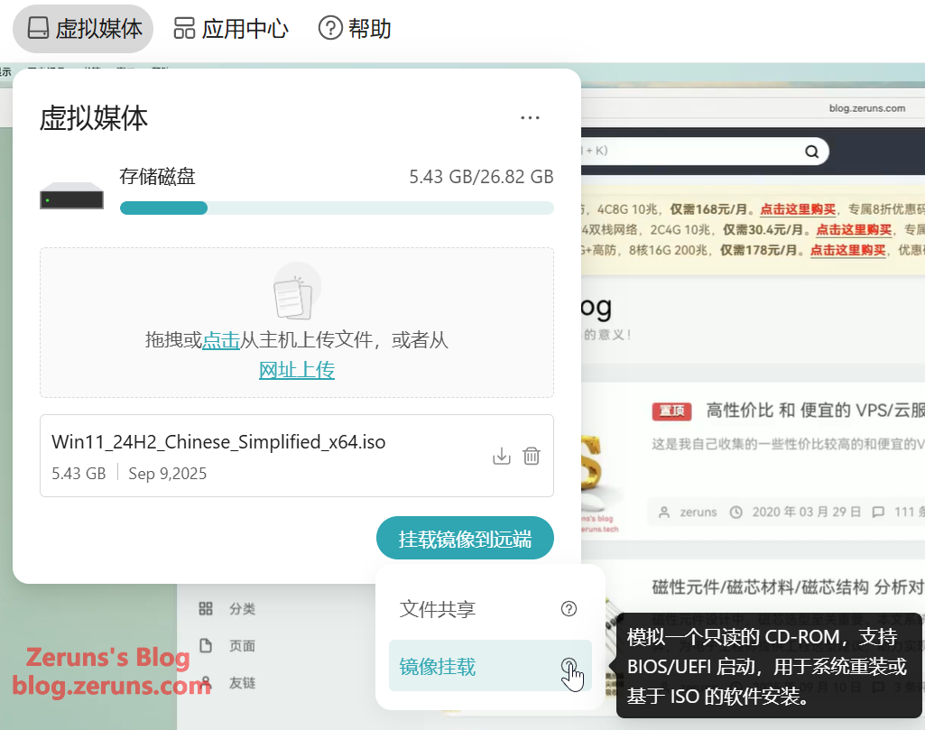
The Virtual Media feature allows you to upload files, emulate a USB drive to transfer files, or emulate a read-only CD-ROM for OS reinstallation.
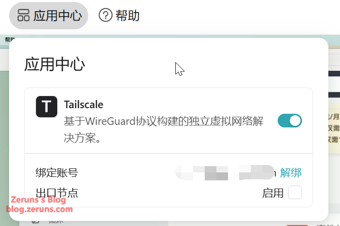
The App Center includes Tailscale for NAT traversal, enabling remote control outside the LAN.
Client screenshots show that remote control works without requiring a public IP.

FGB-01 Finger Robot
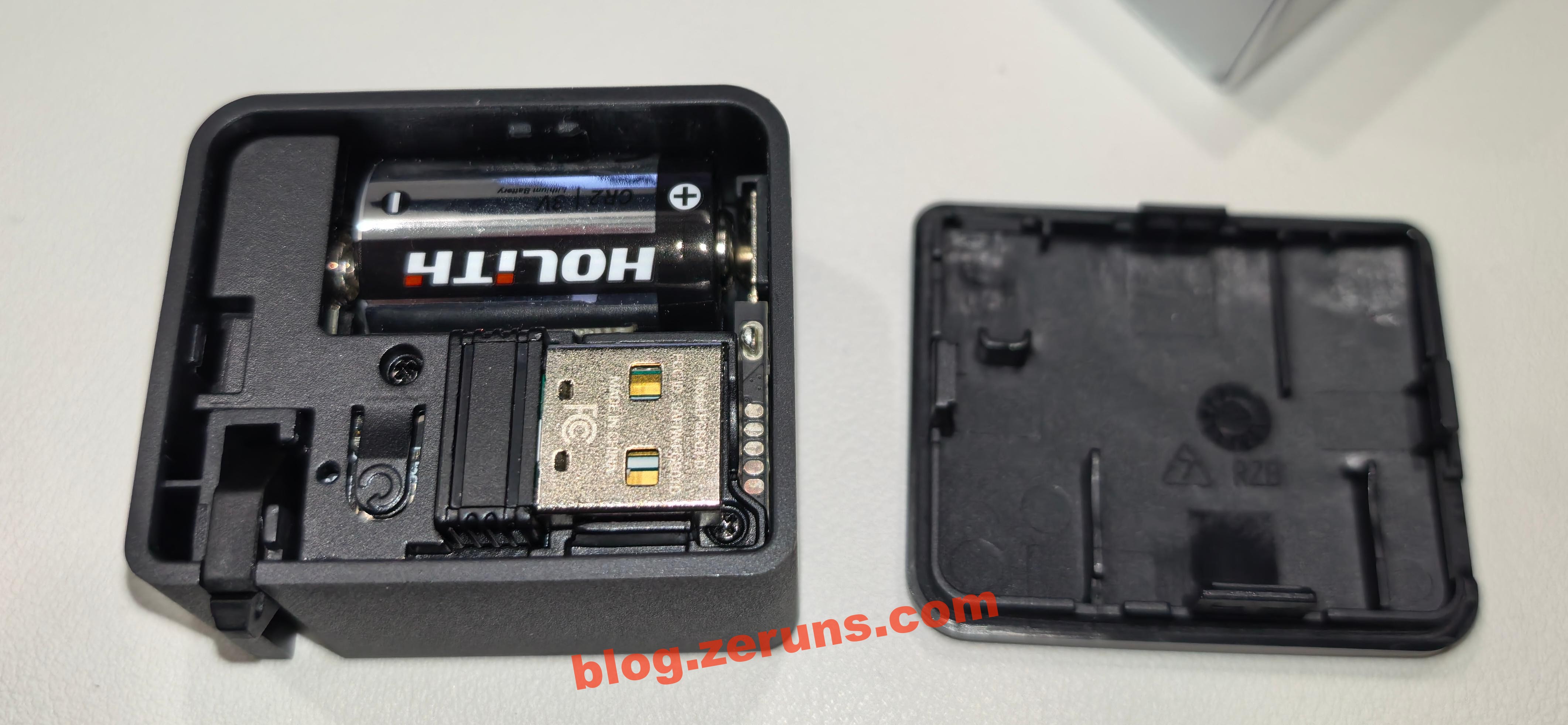
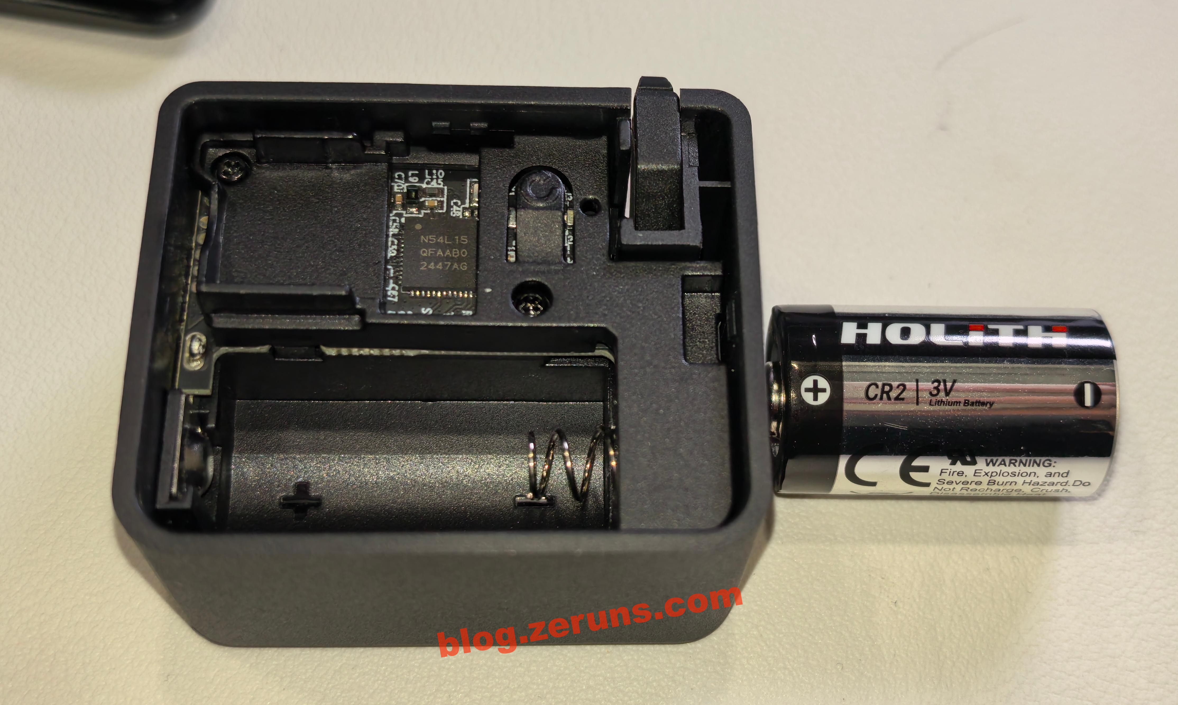
Remove the plastic strip from the battery to activate it. Open the top cover of the Finger Robot to access the USB Bluetooth receiver, plug it into the GL-RM1PE’s USB-A port, and then you can control the Finger Robot via the “External Devices” menu in the control panel.
The Finger Robot is powered by a CR2 battery (3V). You can also replace it with a rechargeable CR2 lithium battery.
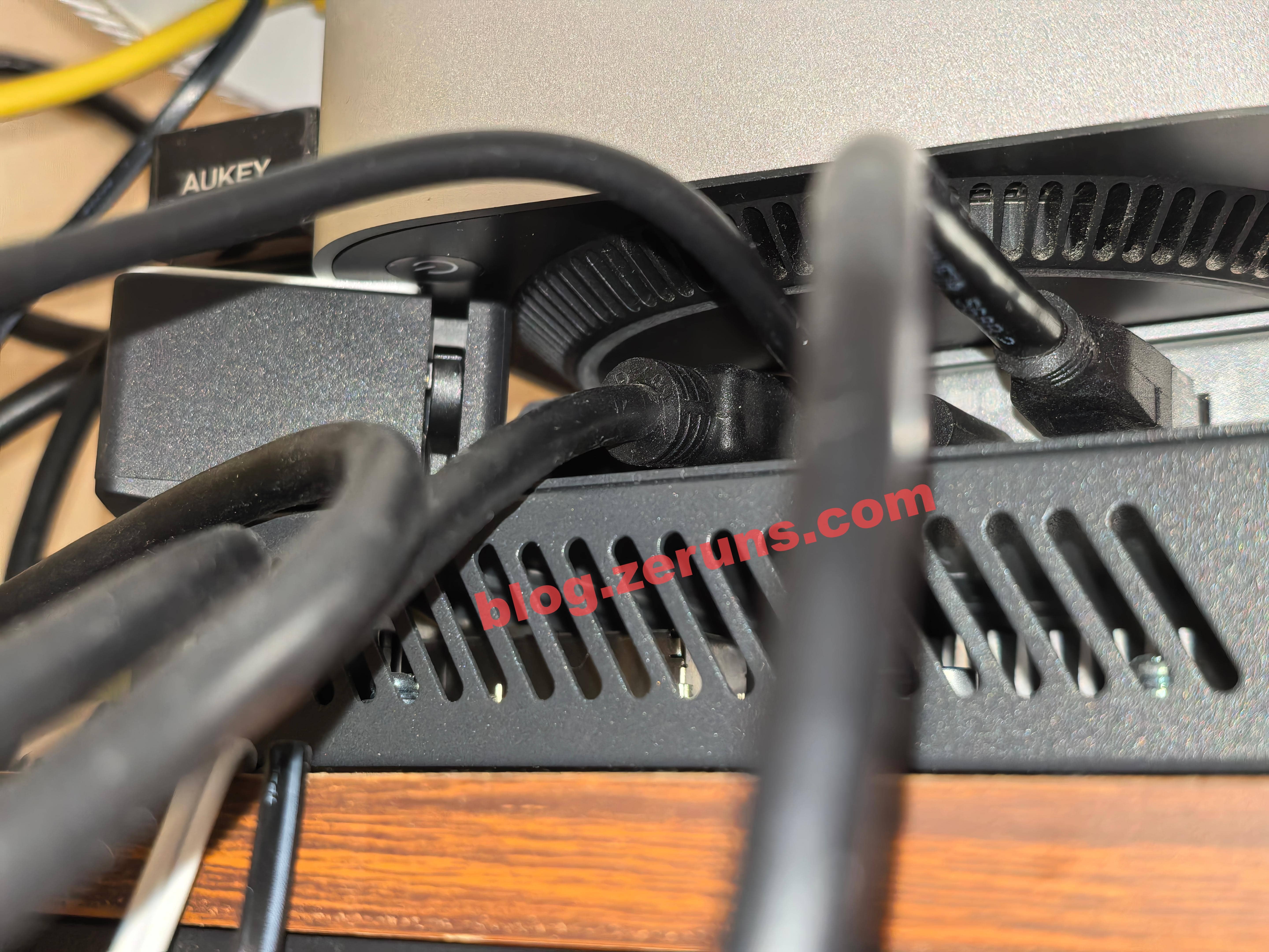
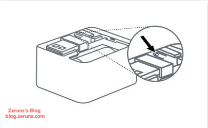
Attach the Finger Robot to the target device, ensuring its actuator can physically reach the power button when pressed. This enables full power control.
There are two press modes: heavy press and light press, with different pressing depths to suit various types of buttons.
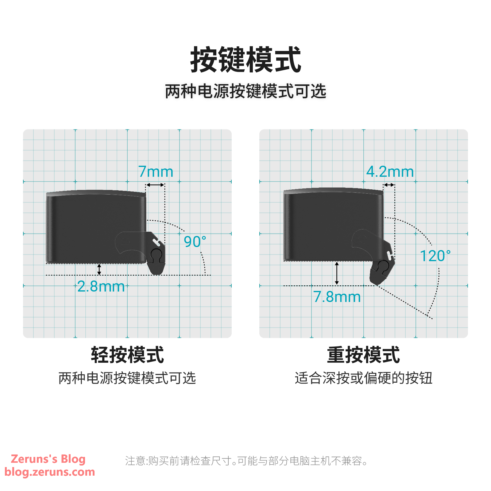
You can also use the test button (inside the Finger Robot, visible when the top cover is removed) to fine-tune your preferred pressing strength.
Teardown
GL-RM1PE
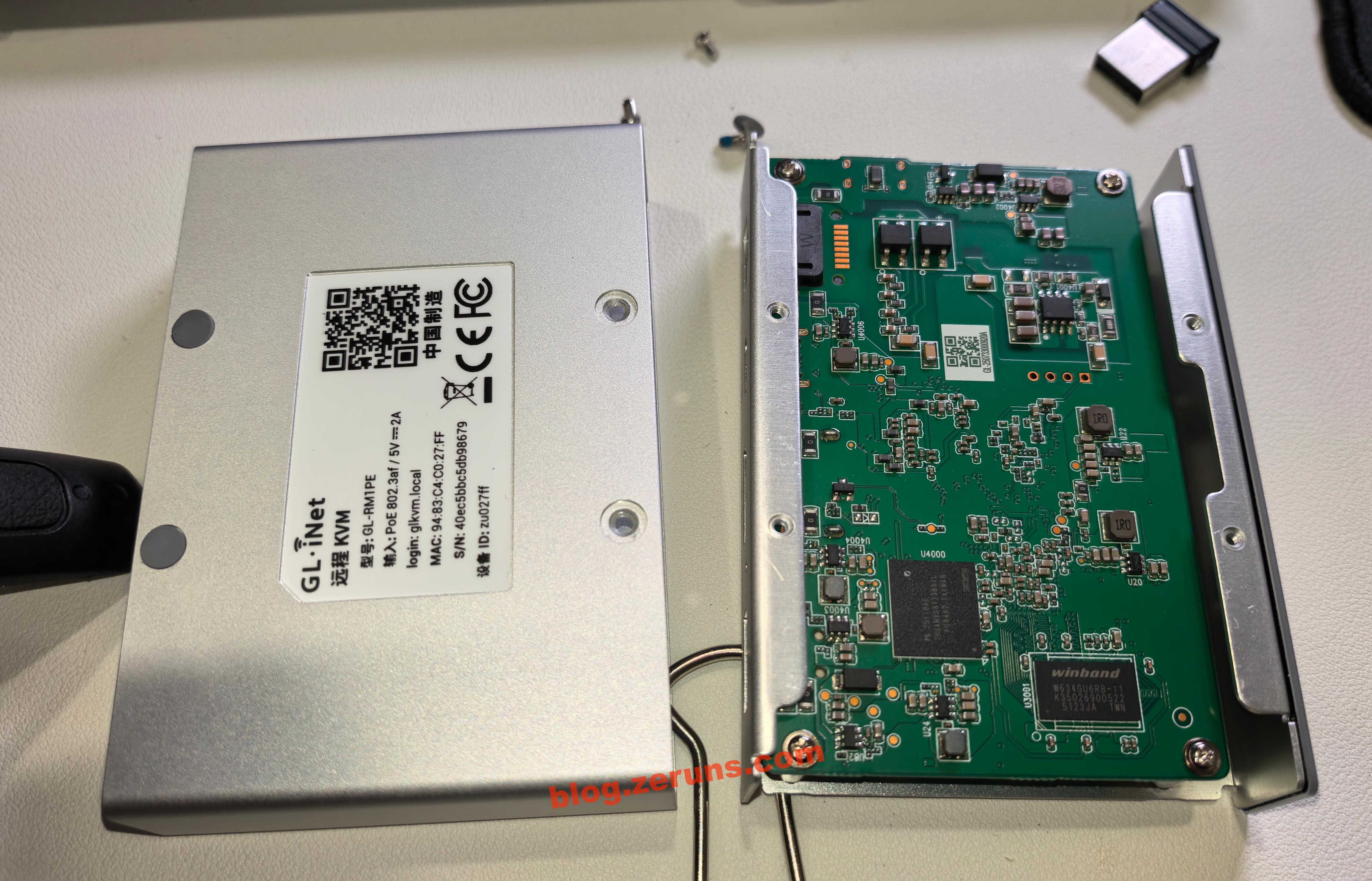
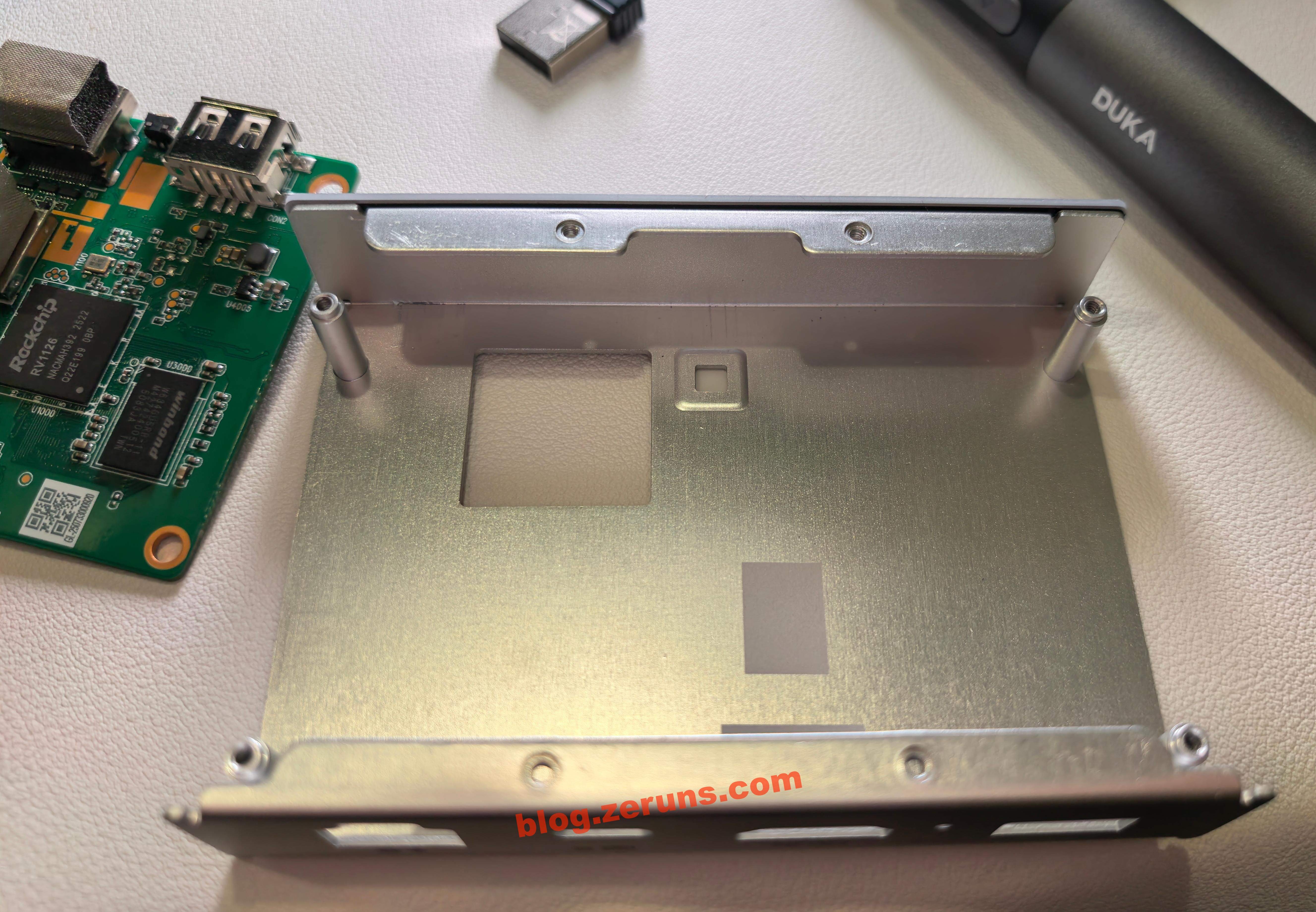
Remove the screws hidden under the four anti-slip pads to take out the motherboard and the internal aluminum frame.
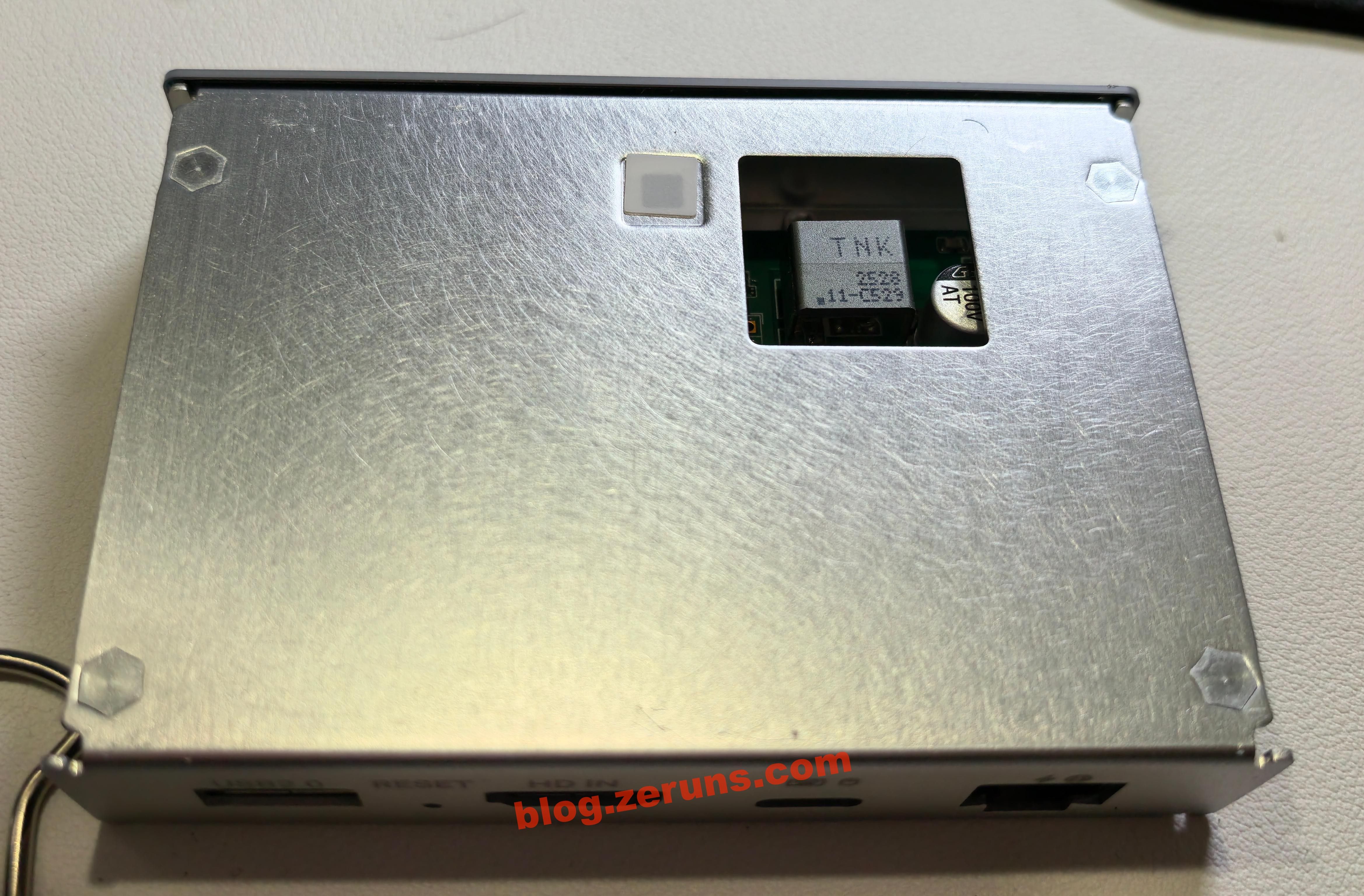
Back of the aluminum frame, with a cutout window for the transformer.
Unscrew the screws on the motherboard and remove the circuit board.
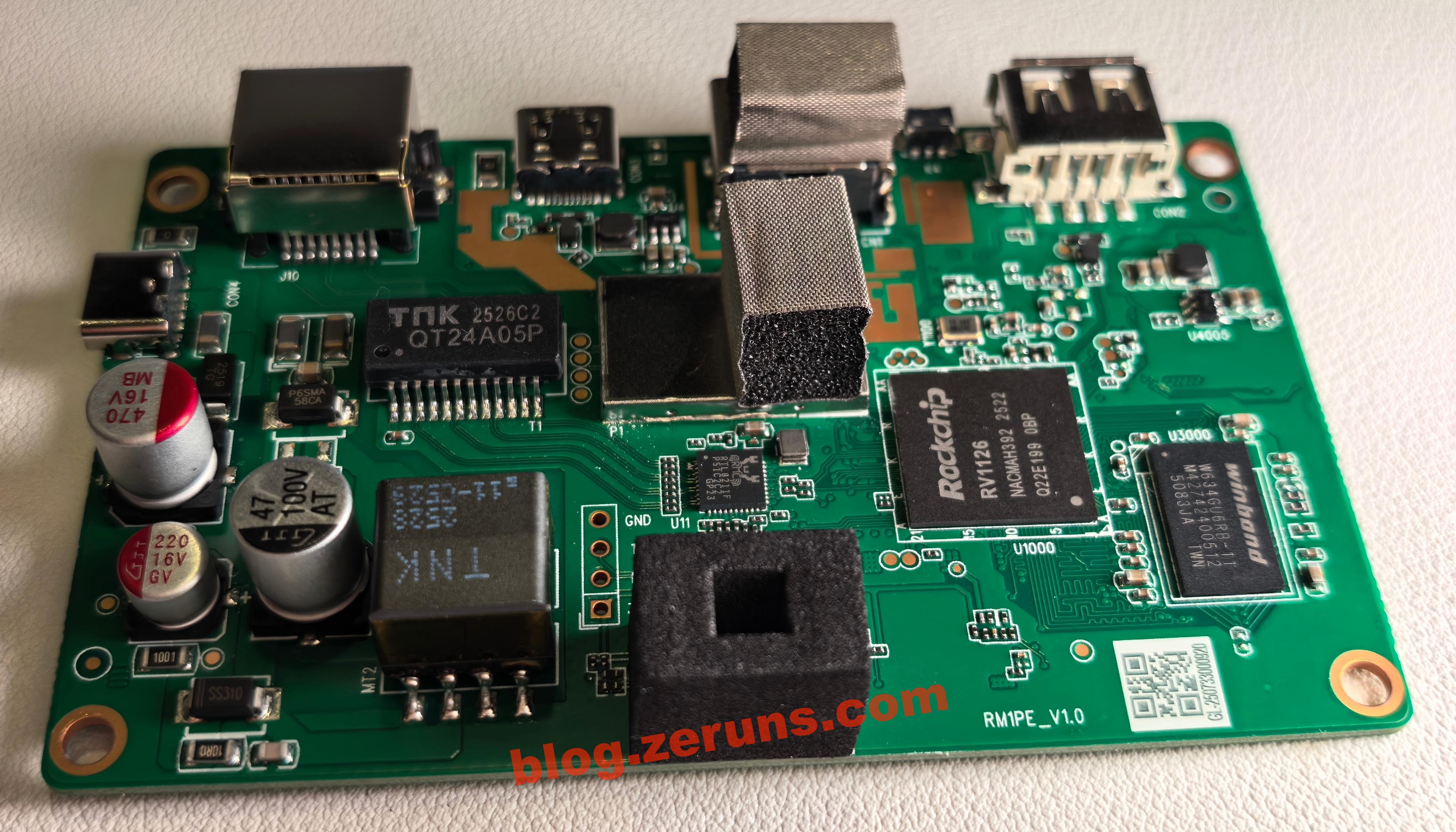
Front side of the motherboard. The PCB vias are resin-filled, which is more expensive than the standard via plug with solder mask.
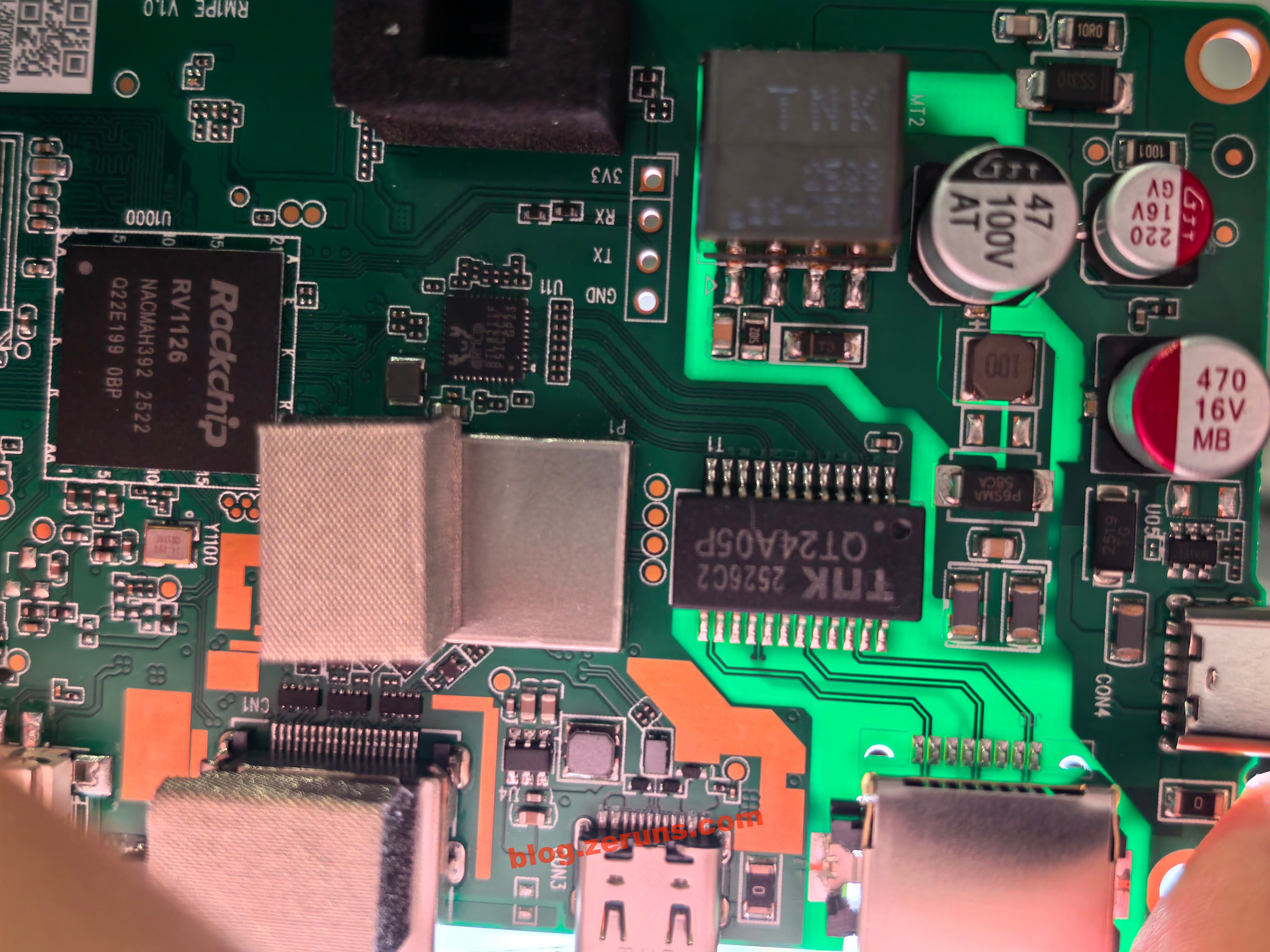
The QT24A05P below the Ethernet port is a single-port Gigabit network transformer with PoE support, produced by TNK (Xunkang Technology).
Below it is another TNK transformer, likely the flyback transformer for PoE power supply based on circuit analysis.
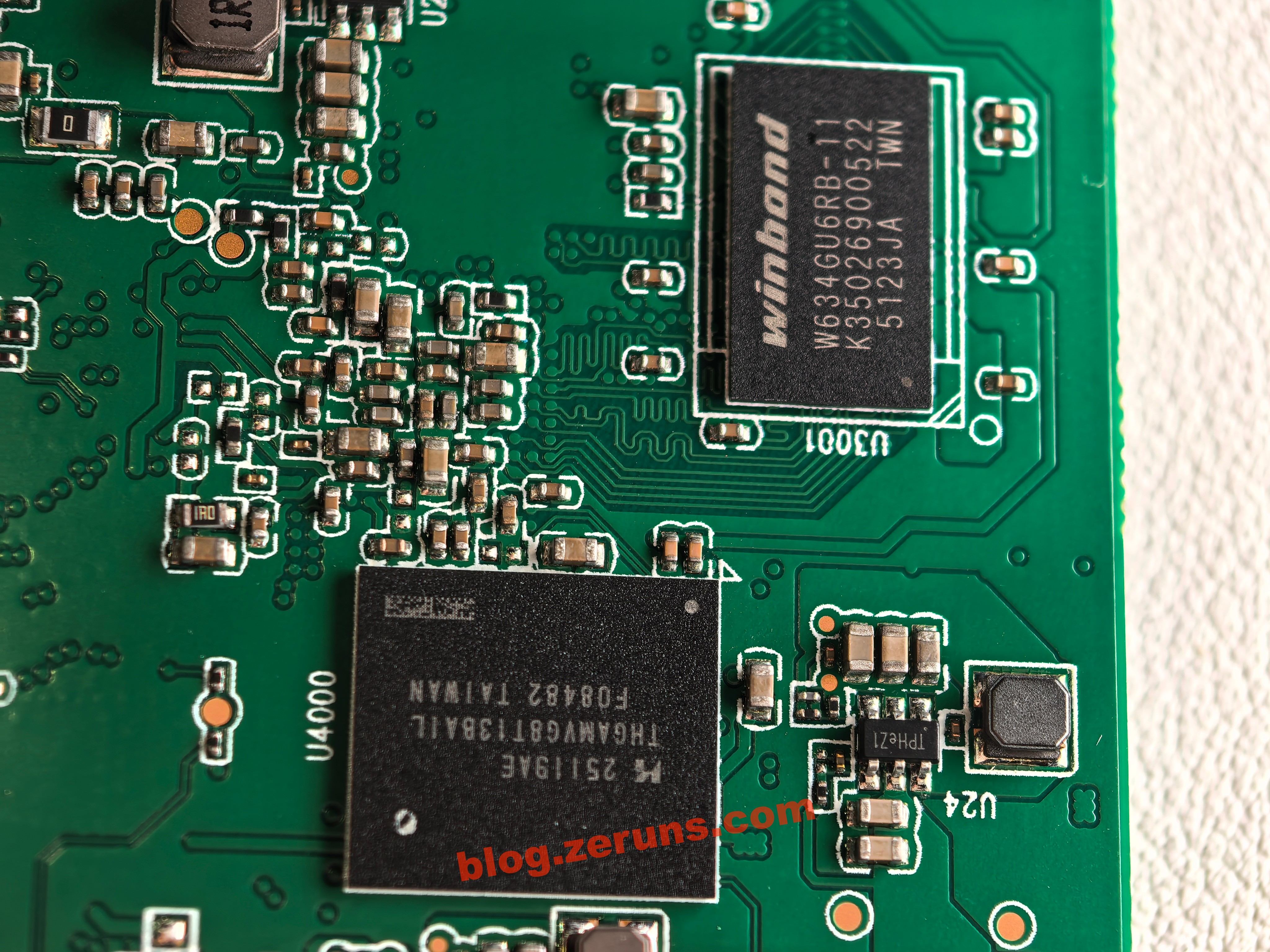
Next to the processor on the right is a W634GU6RB-11 chip, a 4Gbit (512MB) DDR3L memory chip from Winbond. Another identical chip is on the back, totaling 1GB RAM.
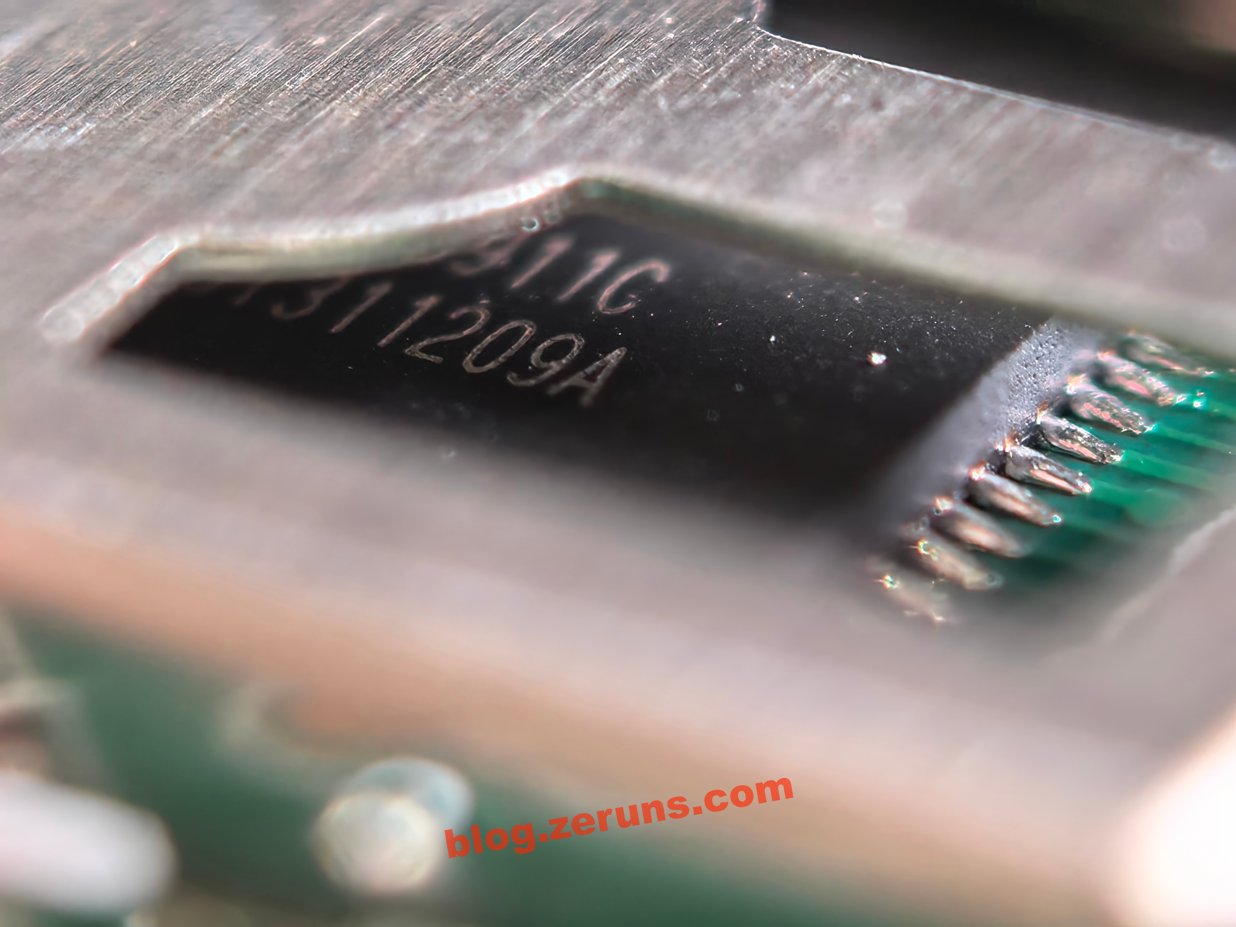
After removing the shielding can next to the HDMI port:
The chip at the lower-right corner is the Rockchip RV1126, a quad-core ARM Cortex-A7 + RISC-V MCU, with a 2.0Tops NPU, 14M ISP, and support for 4K H.264/H.265 video encoding and decoding.
The chip under the shield is the Realtek RTL8211F, a Gigabit Ethernet PHY transceiver.
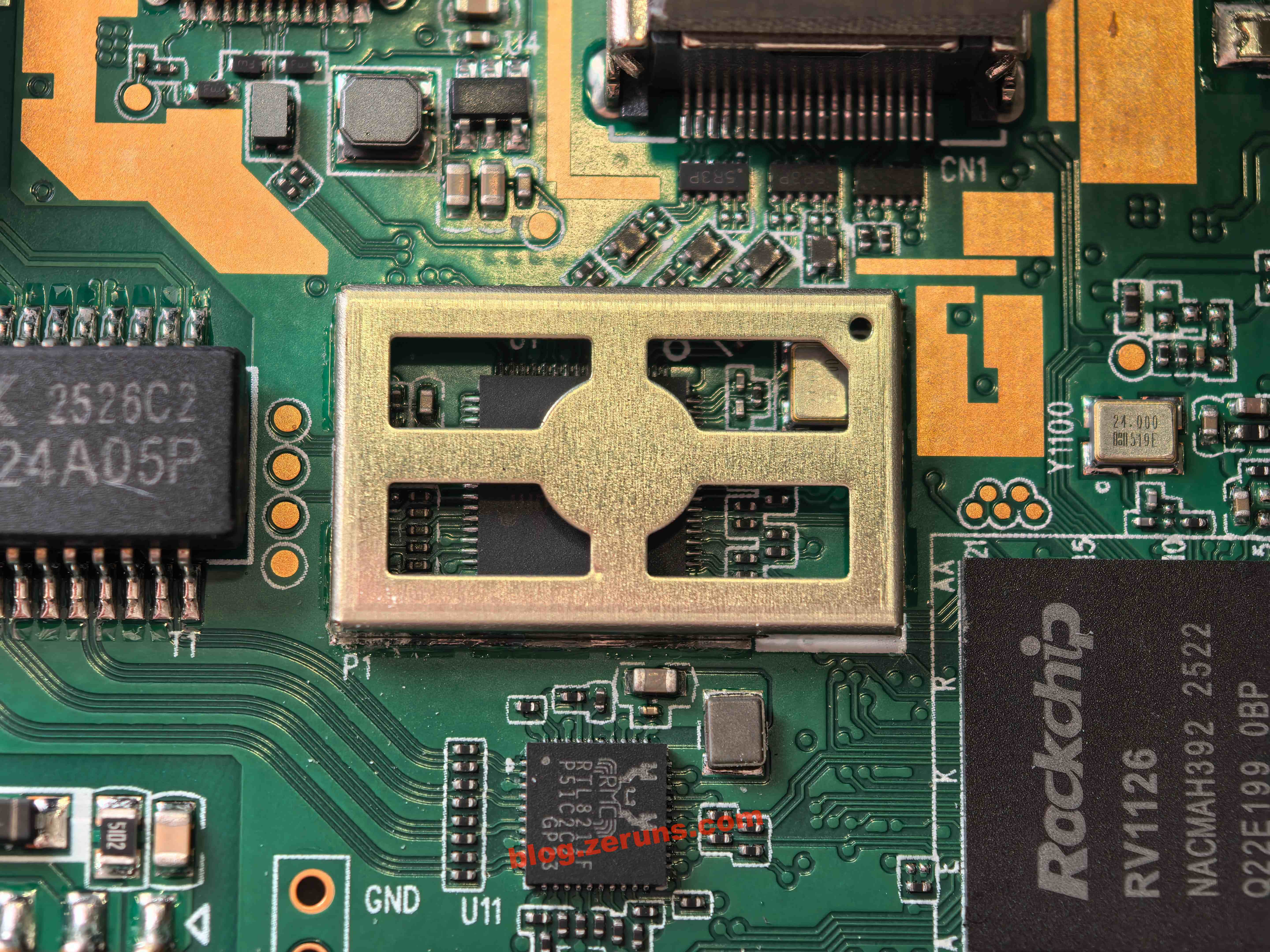
The chip inside the shielding is the LT6911C, an HDMI-to-MIPI/LVDS/CSI bridge from Lontium Semiconductor. It supports HDMI 1.4 and comes with comprehensive audio processing and flexible control interfaces.
Back of the motherboard:
On the left are two bridge rectifiers, likely part of the PoE power circuit. At the top right is the TME7350 chip, a standard PoE Powered Device IC from Tollsemi, supporting IEEE 802.3af PoE with an integrated flyback converter. The flyback transformer is on the front of the board.
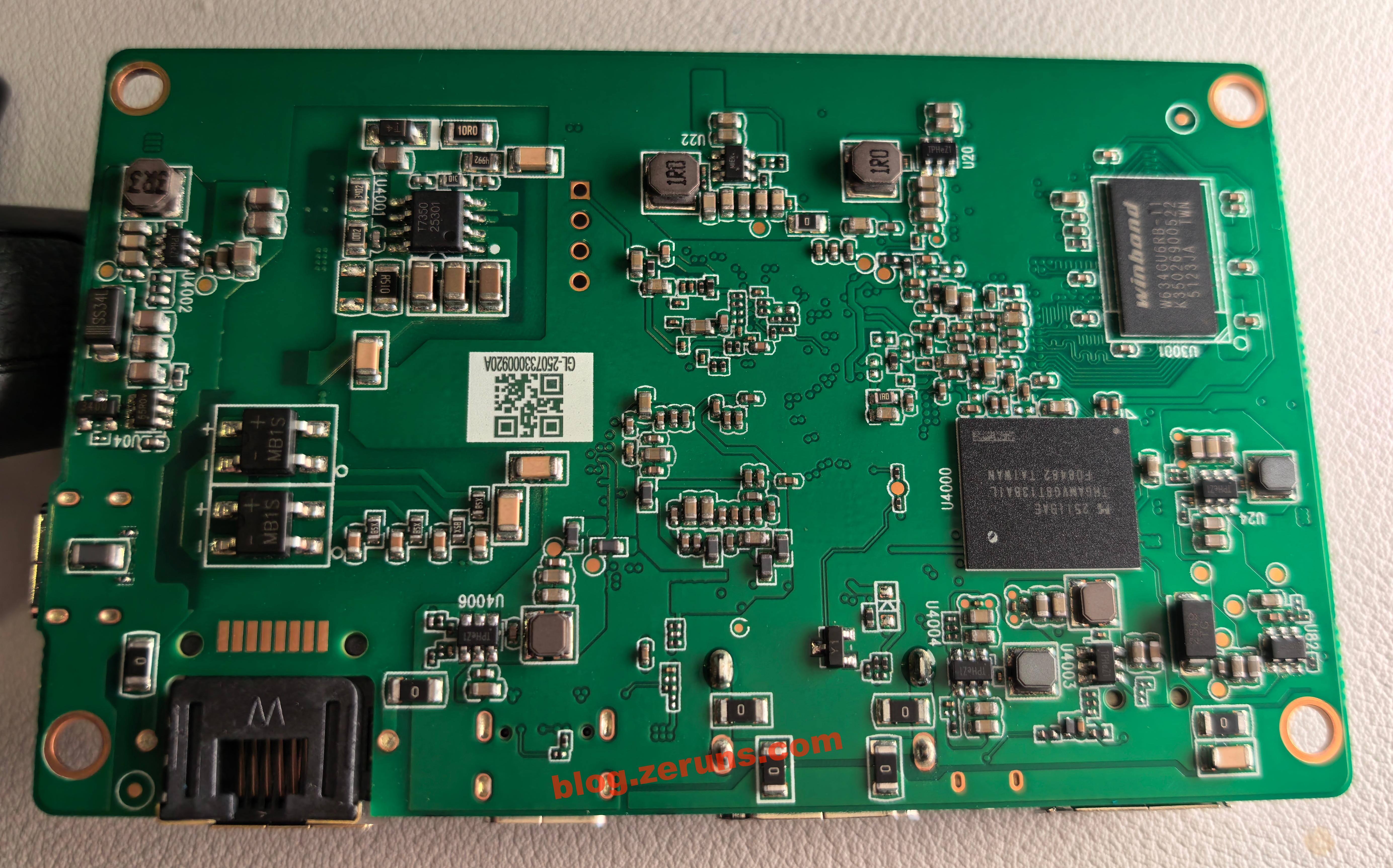
Also on the back is the THGAMVG8T13BAIL chip, a KIOXIA e-MMC 5.1 flash memory with 32GB capacity and up to 400MB/s speed.
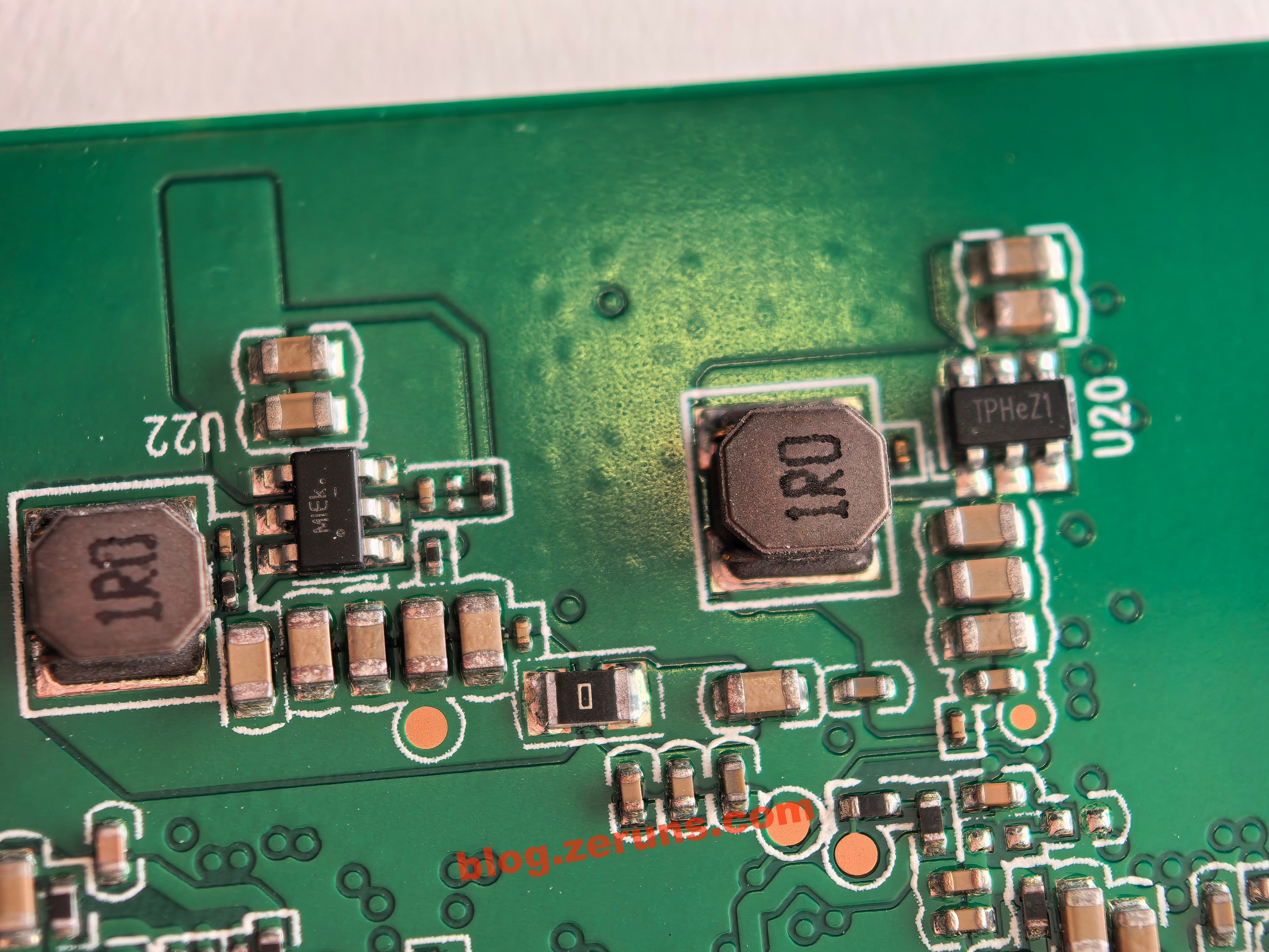
To the right is a DC-DC chip labeled TPHeZ1. Model unknown, no data found.
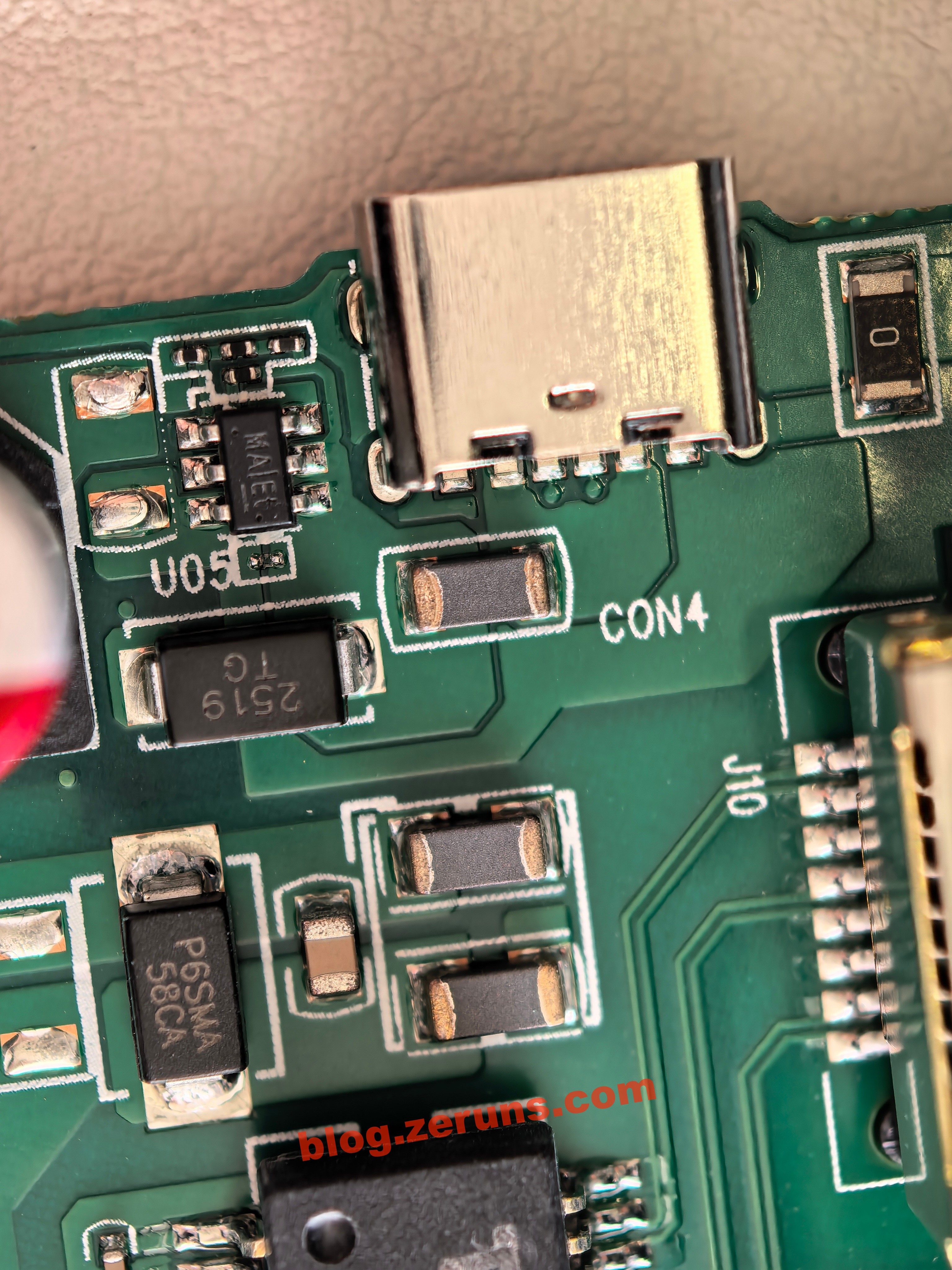
Next to the Type-C power port is a DC-DC chip, with traces indicating a boost converter circuit.
Other DC-DC chips:
Looking through the PCB, internal layers are visible. This is at least a 4-layer board.
FGB-01 Finger Robot
Remove the battery and unscrew the screws.
Disconnect the battery cable and remove the mainboard of the finger robot.
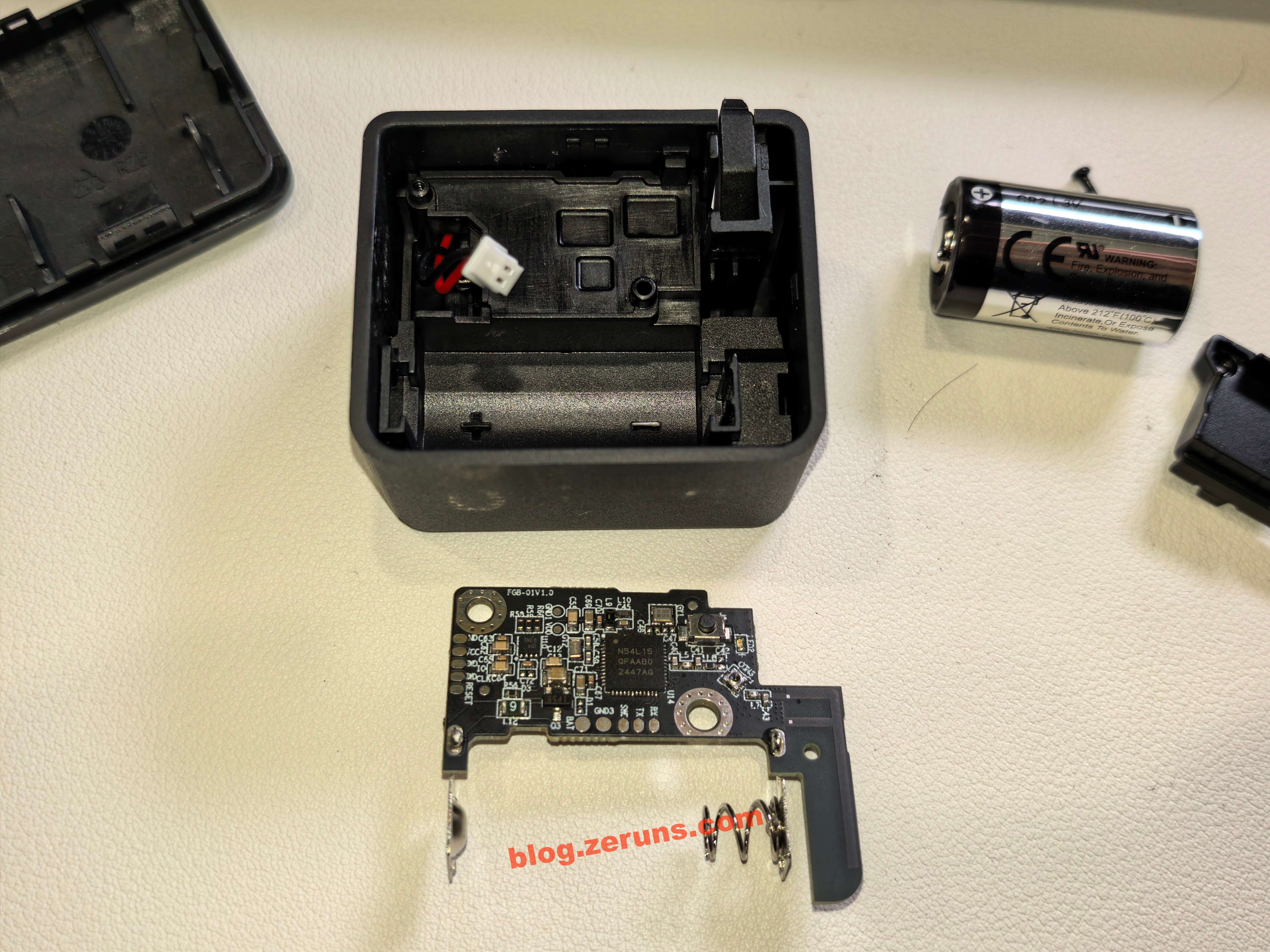
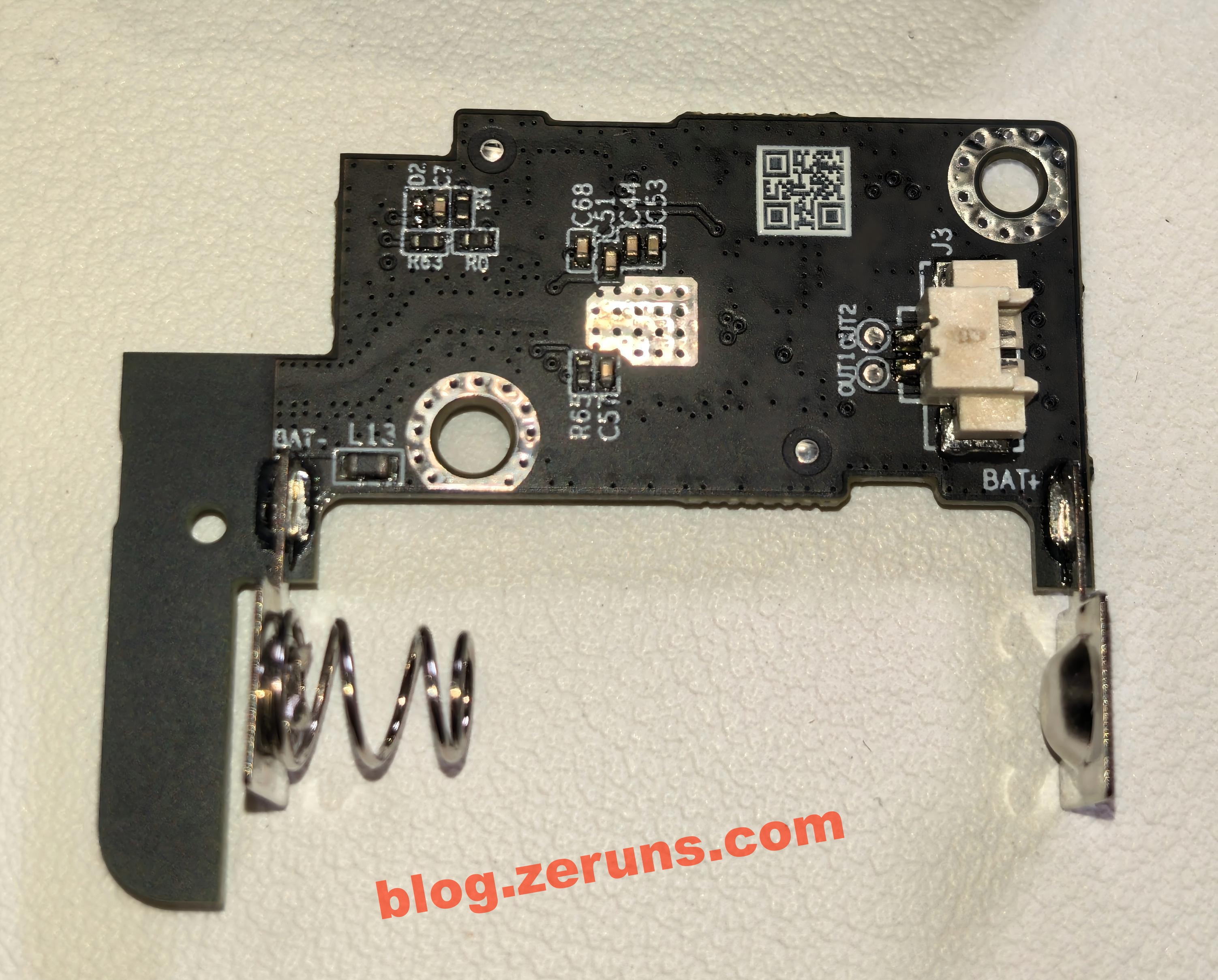
Back of the mainboard:
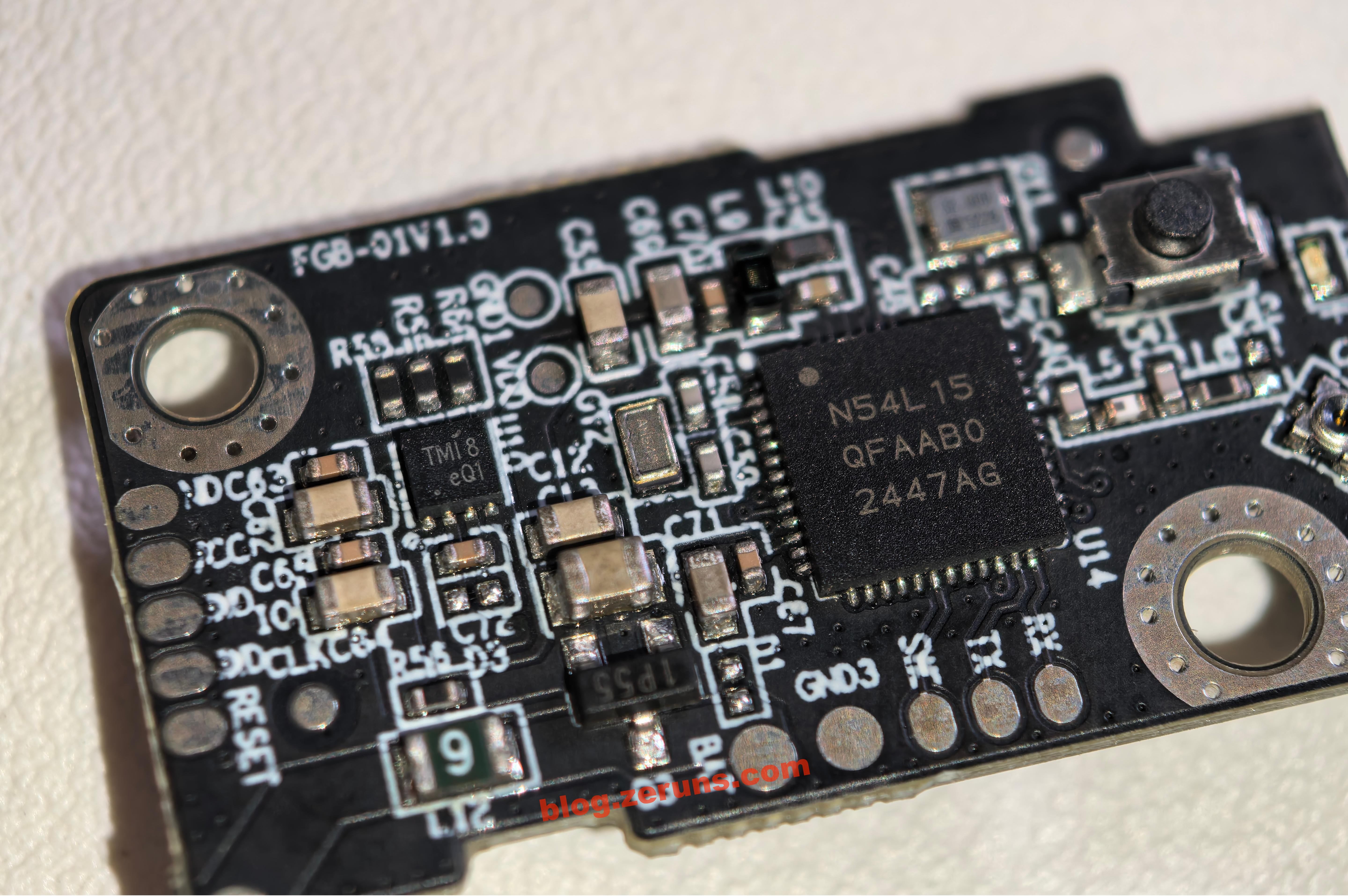
The main control chip is the nRF54L15 from Nordic Semiconductor, an ultra-low-power multiprotocol wireless SoC built on a 22nm process. It integrates a 128MHz Arm Cortex-M33 processor with a RISC-V coprocessor, supporting Bluetooth 5.4/6.0, Thread, and Matter. It comes with 1.5MB NVM and 256KB RAM, RF performance of +8dBm TX power and -98dBm RX sensitivity, PSA Level 3 security certification, and ultra-low-power design, suitable for smart home and industrial IoT applications.
On the left is a chip marked TMI8, likely a brushed DC motor driver. The model is suspected to be TMI8870D or TMI8180D.
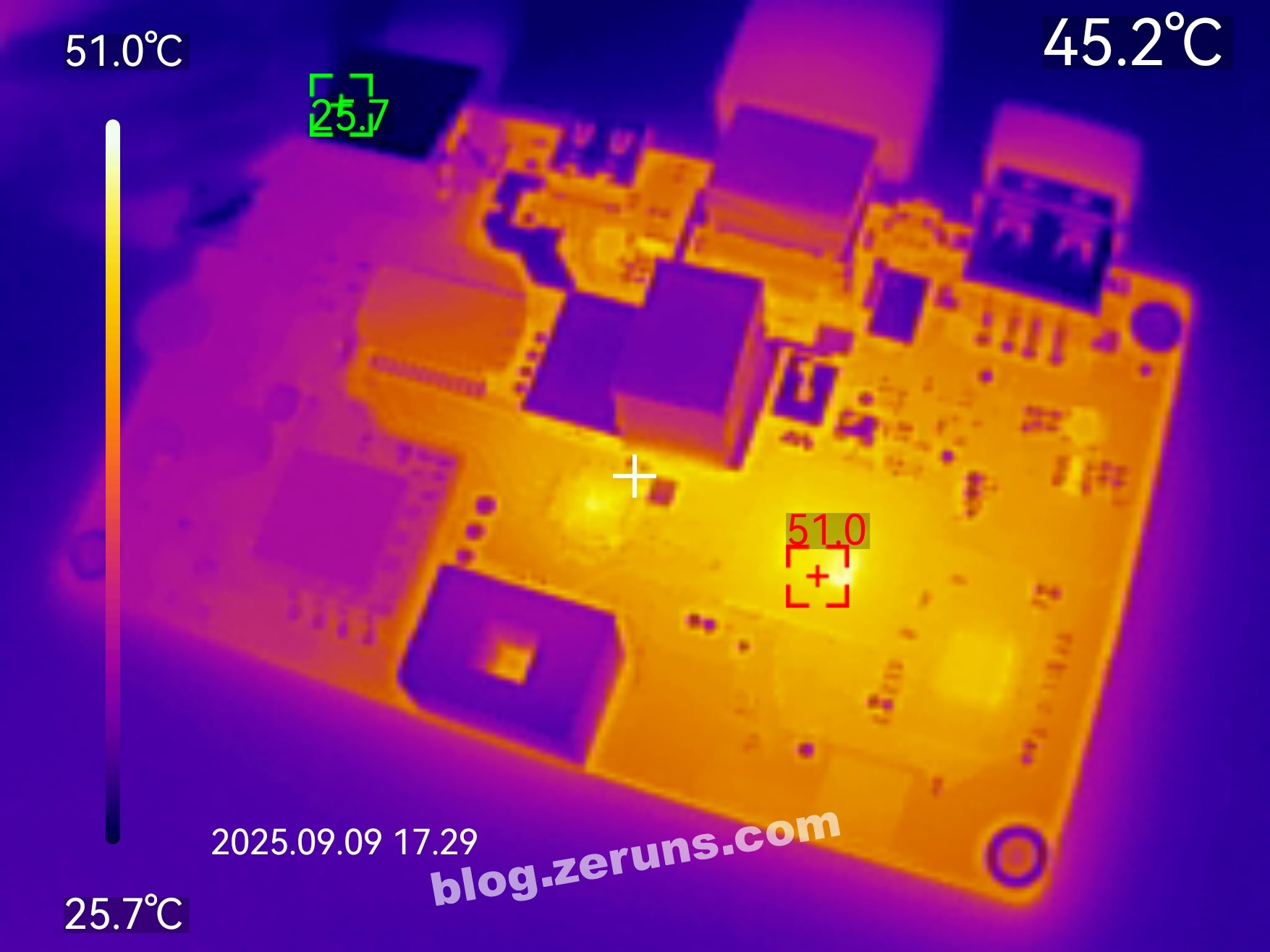
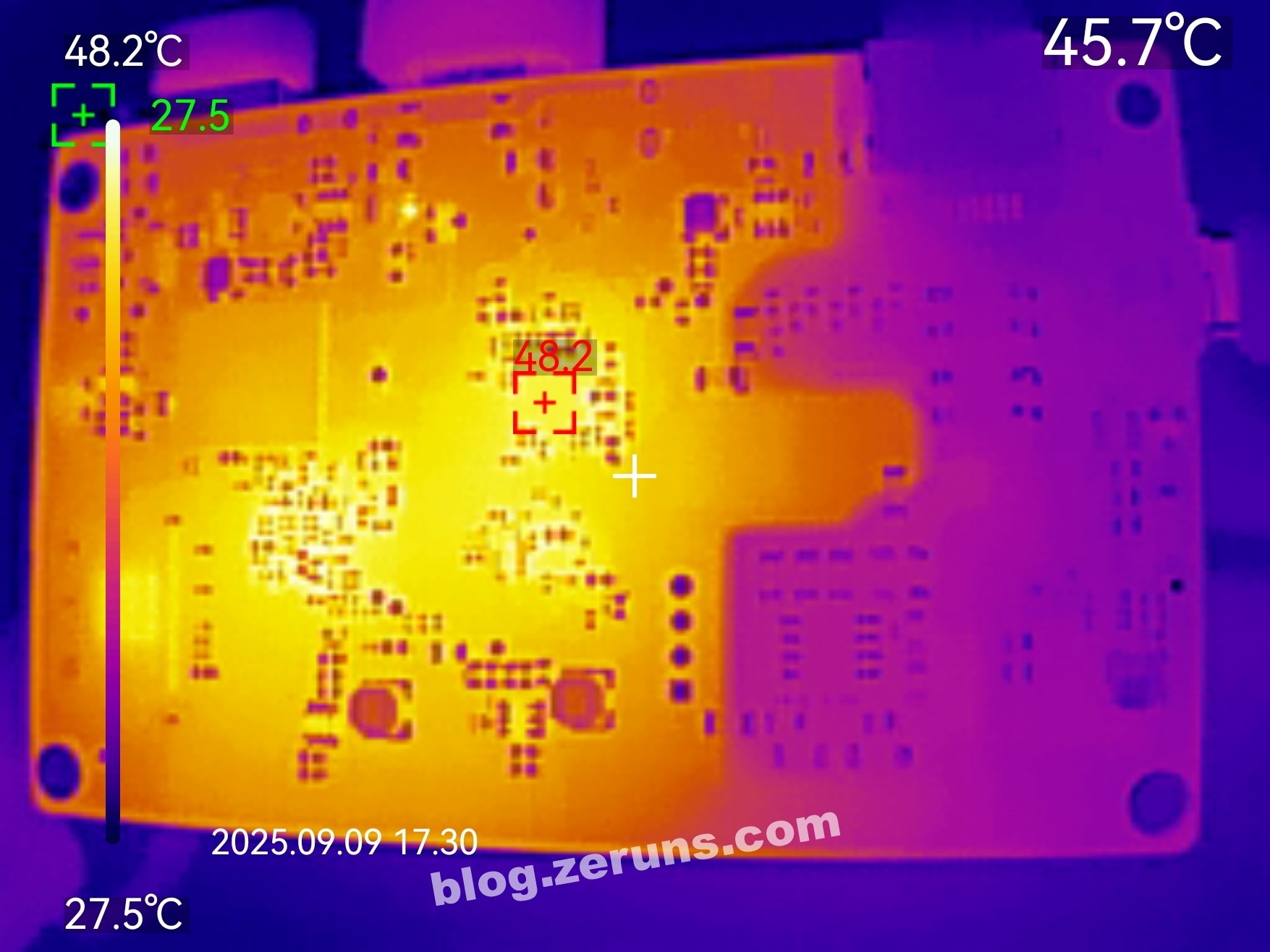
Thermal Imaging
Thermal imaging test using the UNI-T UTi261M thermal imager: https://blog.zeruns.com/archives/798.html
Thermal image of the front side of the motherboard after running HDMI for a few minutes. Room temperature ~26°C, processor temperature ~51°C.
Back side thermal image, hottest spot under the HDMI converter chip, ~48°C.
Recommended Reading
- Cost-effective and affordable VPS/Cloud Server Recommendations:https://blog.zeruns.com/archives/383.html
- Minecraft Server Hosting Tutorials: https://blog.zeruns.com/tag/mc/
- NanoKVM Unboxing and Teardown: https://blog.zeruns.top/archives/26.html
- Mechrevo Code10AI Laptop (Ultra7-255H) Unboxing and Teardown: https://blog.zeruns.top/archives/66.html
- Cross-border E-commerce Website Setup Tutorial, WordPress Guide: https://blog.zeruns.top/archives/64.html


Comment Section