


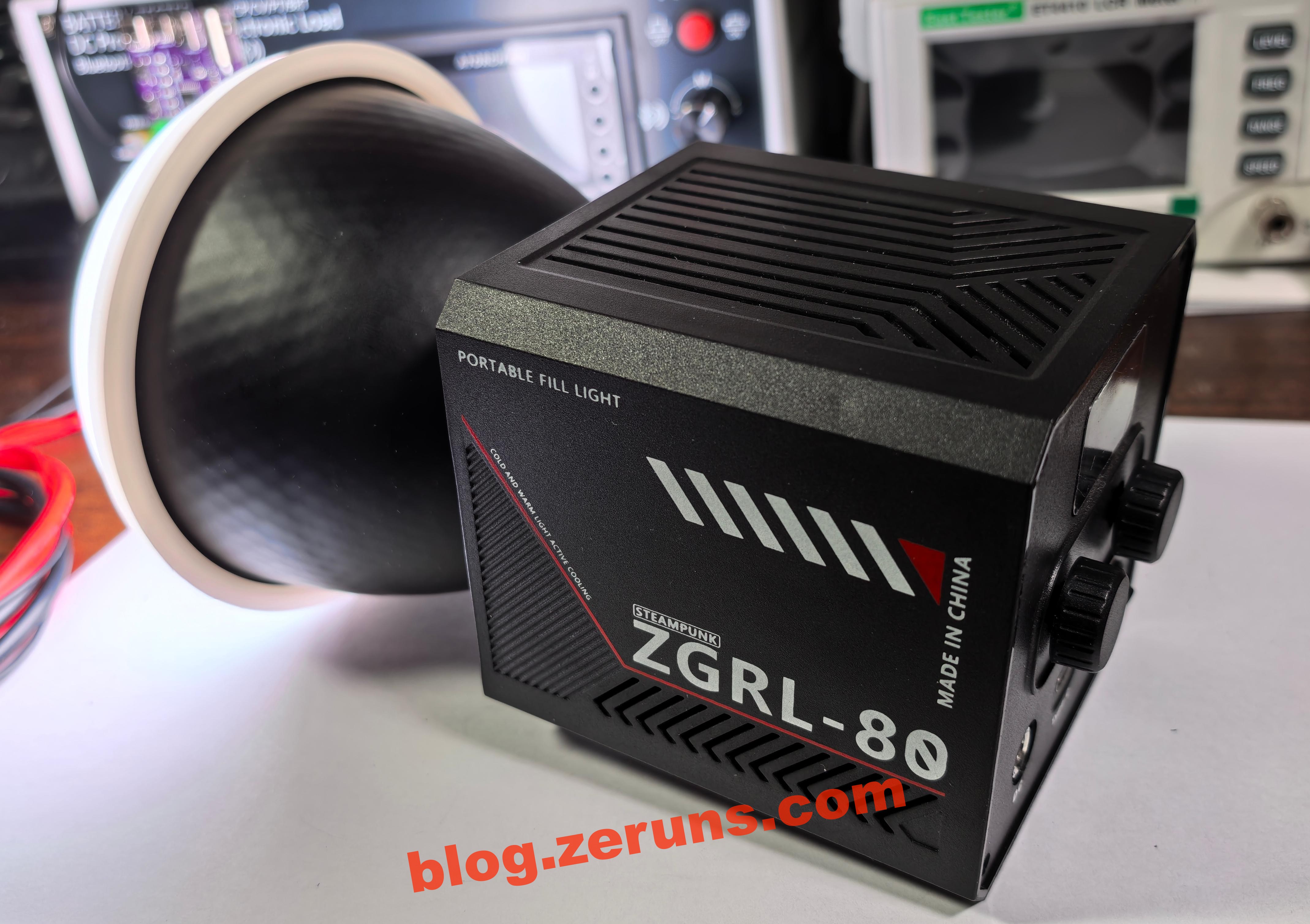
ZGRL-80 Photography Light / Portable Handheld COB Fill Light – Detailed Teardown and Circuit Analysis
Disassembly video: https://www.bilibili.com/video/BV1BR3bztE32/
Preface
On December 16, 2024, I purchased the ZGRL-80 fill light from the 比奥斯数码专营店 on Tmall for 188 CNY. The listed specs claimed 80W power, support for 65W PD fast charging (later proven exaggerated), and a 10,000mAh battery.
After filing a complaint with Taobao customer service, I only received a 100 CNY coupon. The seller faced no penalties and the product remained on sale, with only the "65W PD fast charging supported" line removed from the listing.
▶Electronics / MCU Technology QQ Group: 2169025065
- STM32-based Synchronous Buck-Boost Digital Power Supply (Open Source): https://blog.zeruns.top/archives/1
- Open Source Type-C Dock with 4x10Gbps USB-A + 2.5G NIC + Card Reader: https://blog.zeruns.top/archives/53.html
- Open Source 140W+65W Buck-Boost PD3.1 Charging Module (2C+1A Ports): https://blog.zeruns.top/archives/11
Spec Discrepancies
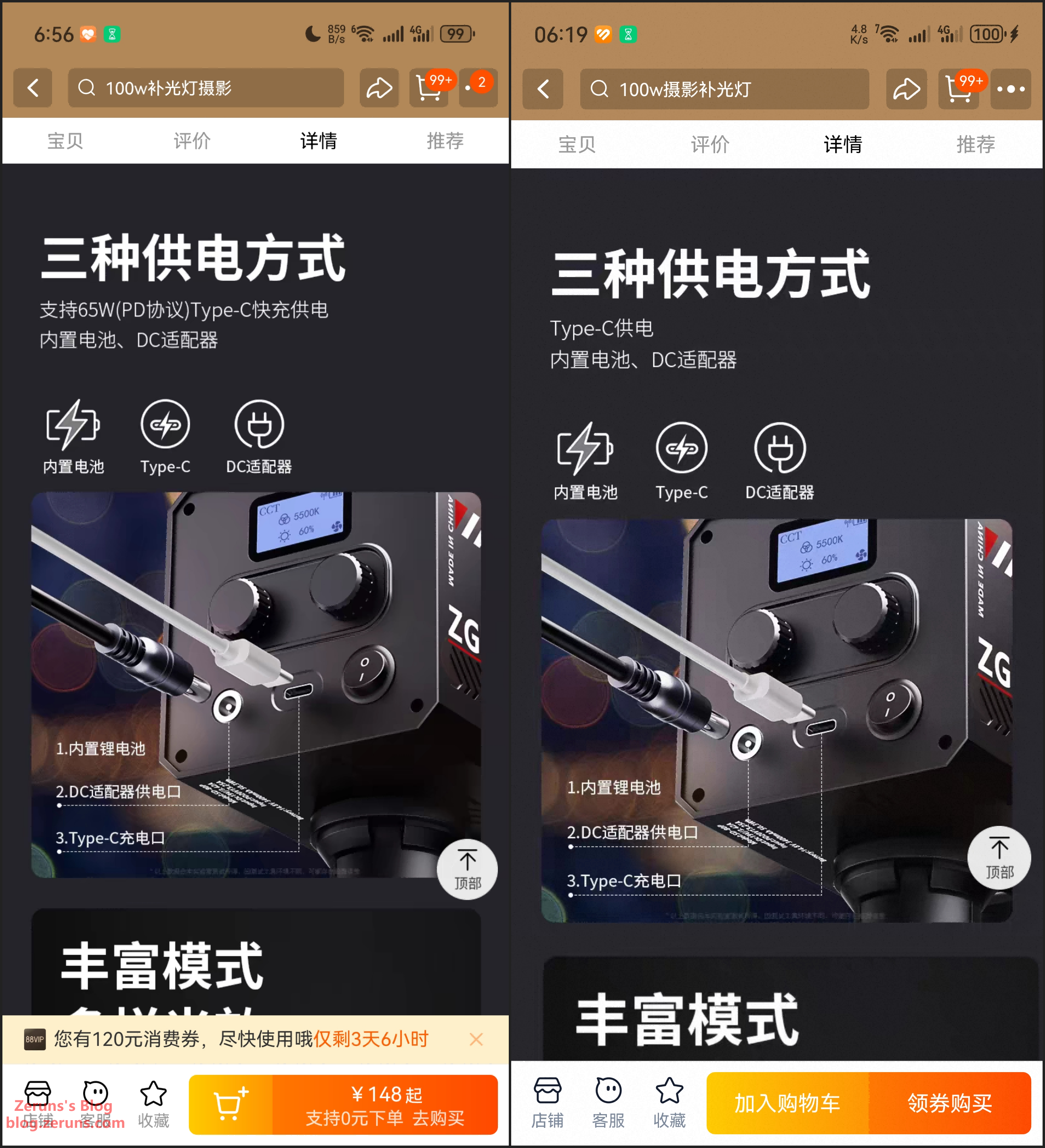
At the time of purchase (Dec 16, 2024), the product page clearly stated supports 65W (PD protocol) Type-C fast charging, but as of today (July 1, 2025), that line has been changed to just Type-C charging. Does this imply a tacit admission of false advertising? (I have transaction snapshots to prove it wasn’t photoshopped.)
Also, the product images claim "80W high power", while the listed specs say 60W — a contradiction.
The listed manufacturer: 深圳市美美一族科技有限公司

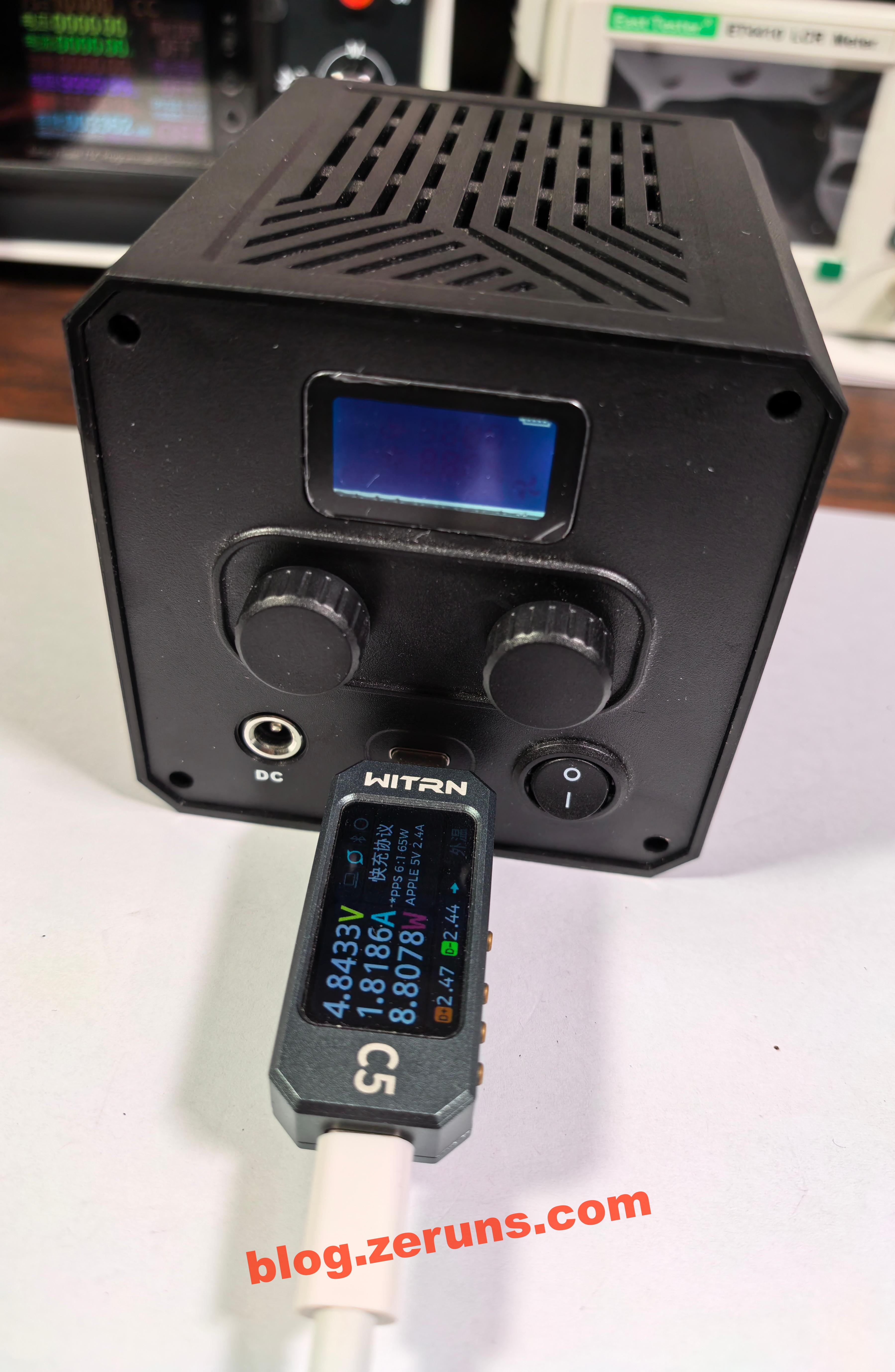
Testing the ZGRL-80 with a 65W PD charger results in a charging power of less than 5V 2A, even when the light is turned on. (As the teardown will show, it indeed does not support fast charging.)
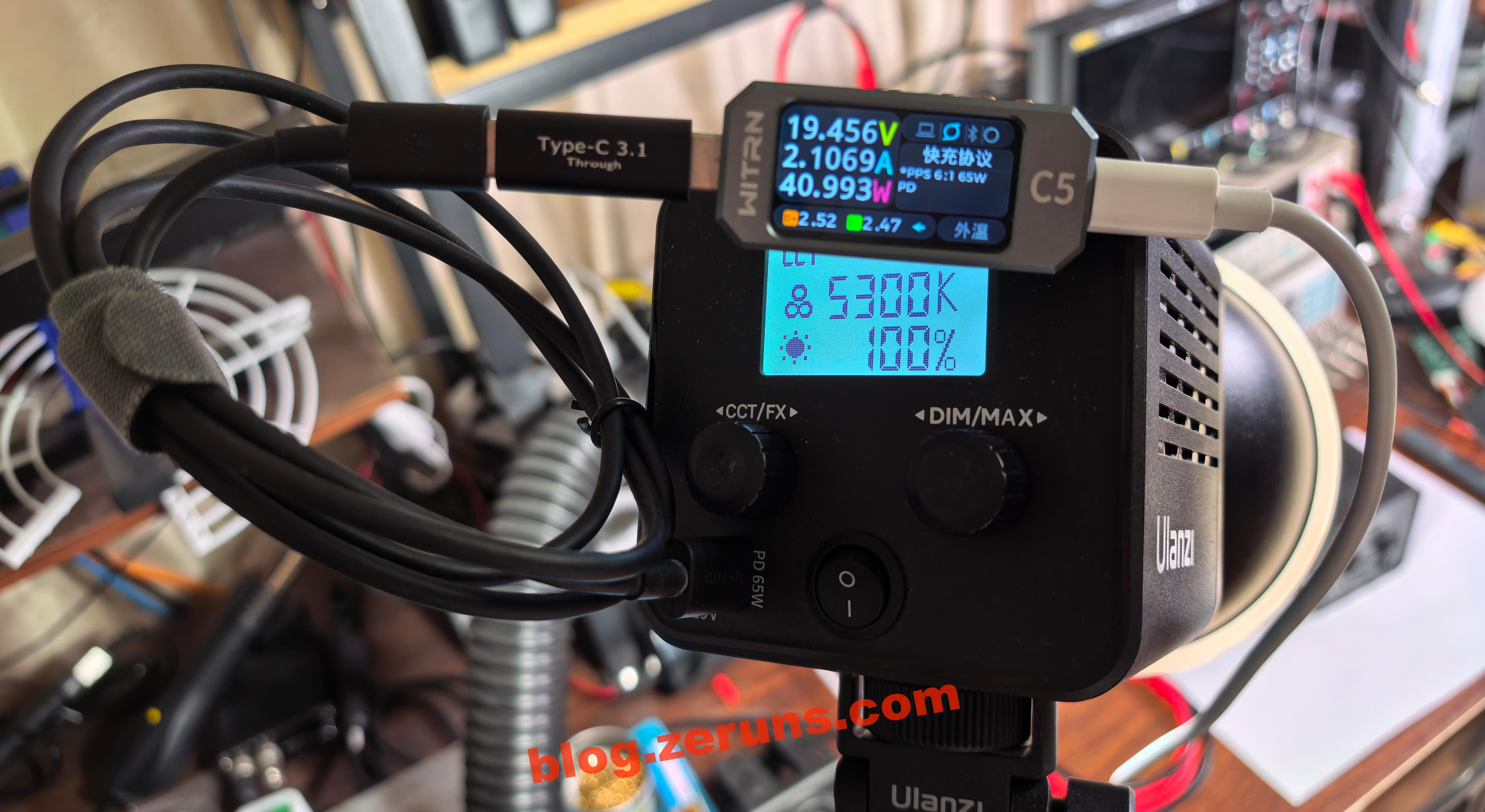
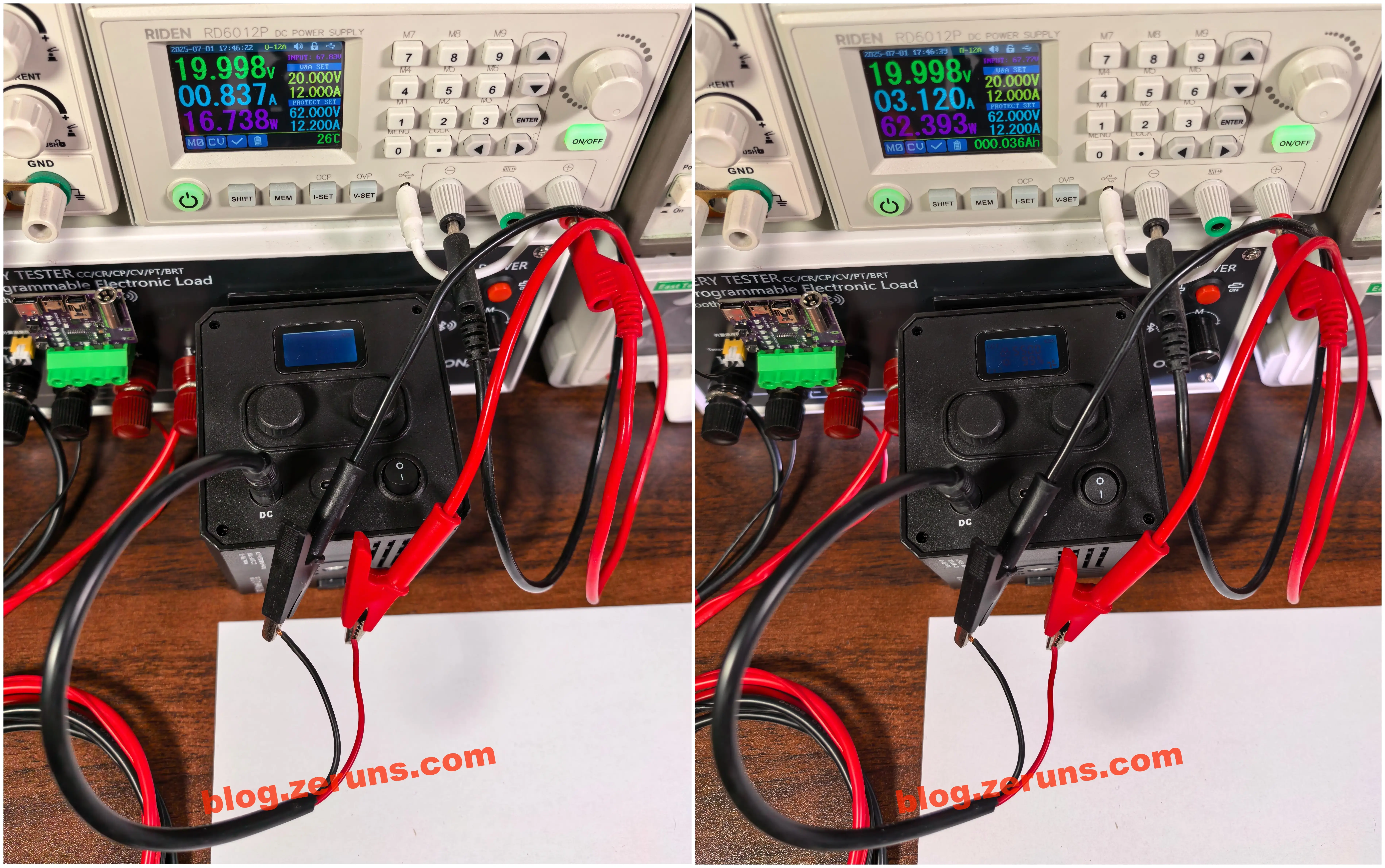
Another fill light I purchased also claimed to support 65W PD charging, and in actual testing, it successfully negotiated PD to output 20V. Since the light is 40W and the battery was already full, the displayed power is only 40.9W.
Feeding 20V into the DC port of the ZGRL-80 yields a charging power of 16.7W. With the light on at 100% brightness and mid-range color temperature, total power consumption (charging + LEDs) is 62.3W. This suggests the LEDs themselves only consume about 40W — another spec exaggeration.
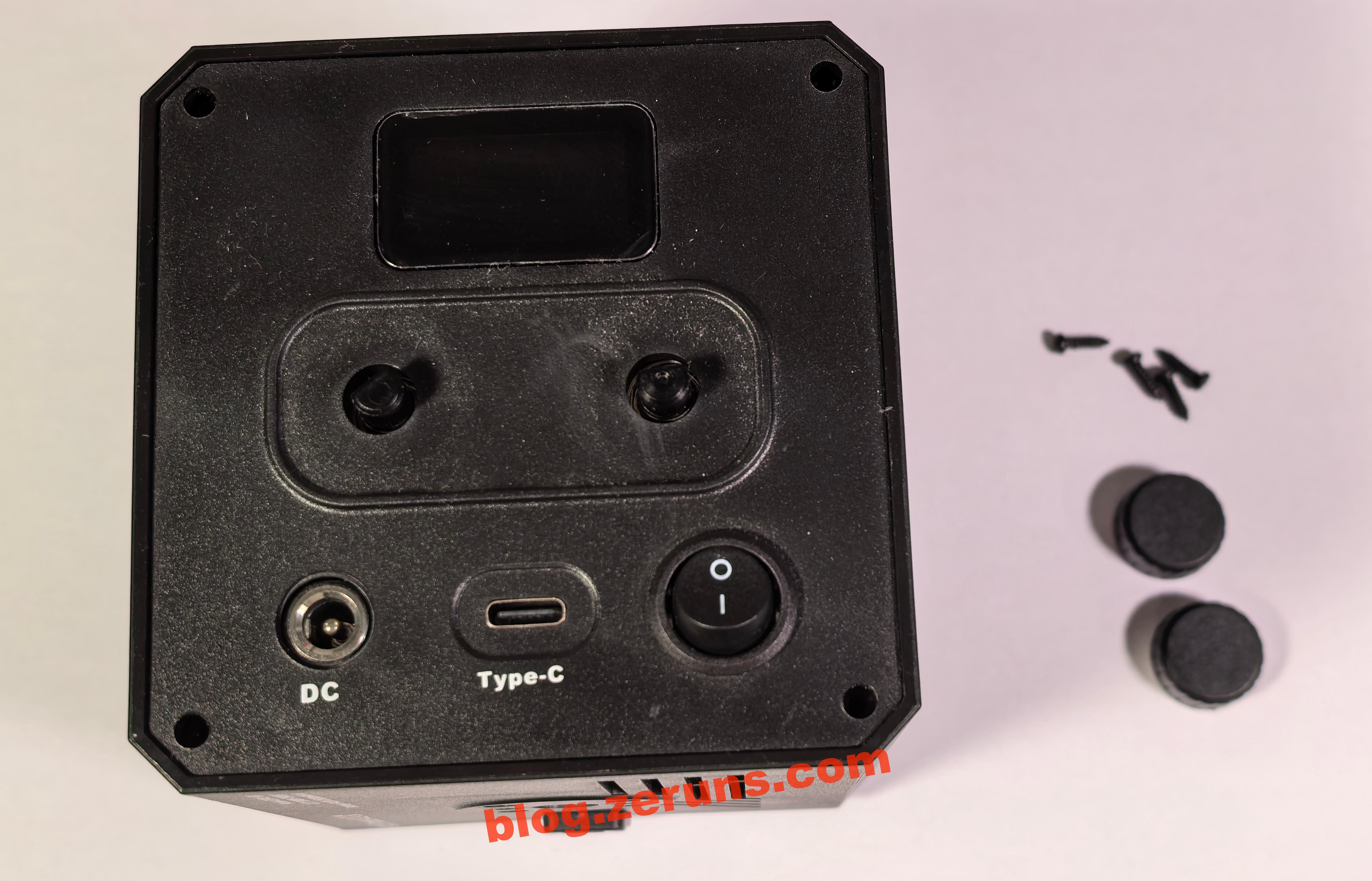
Disassembly
Remove the two knob caps and unscrew the four screws on the screen side.
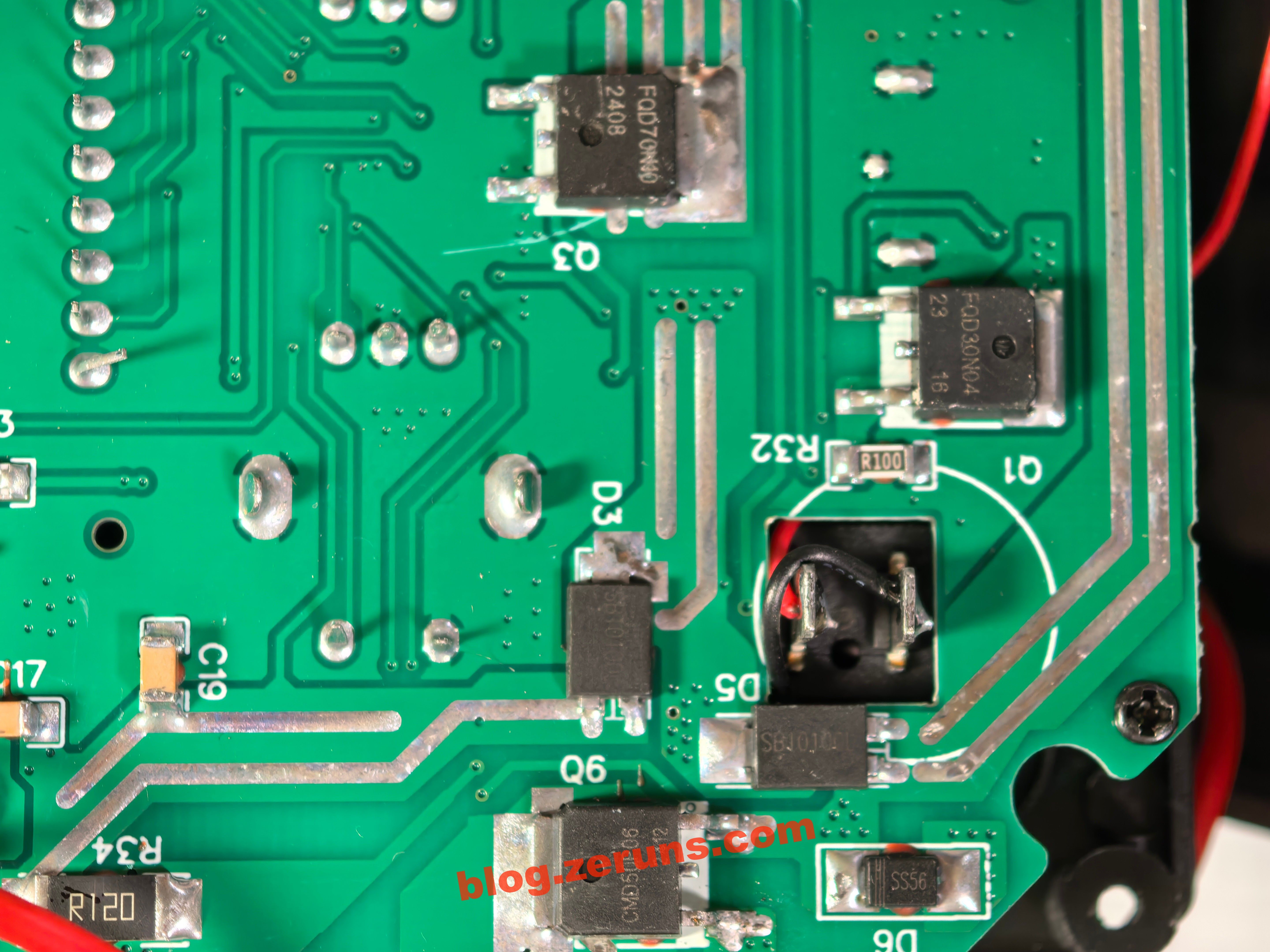
You’ll see the back of the PCB with several wires connected to the LED module and battery.
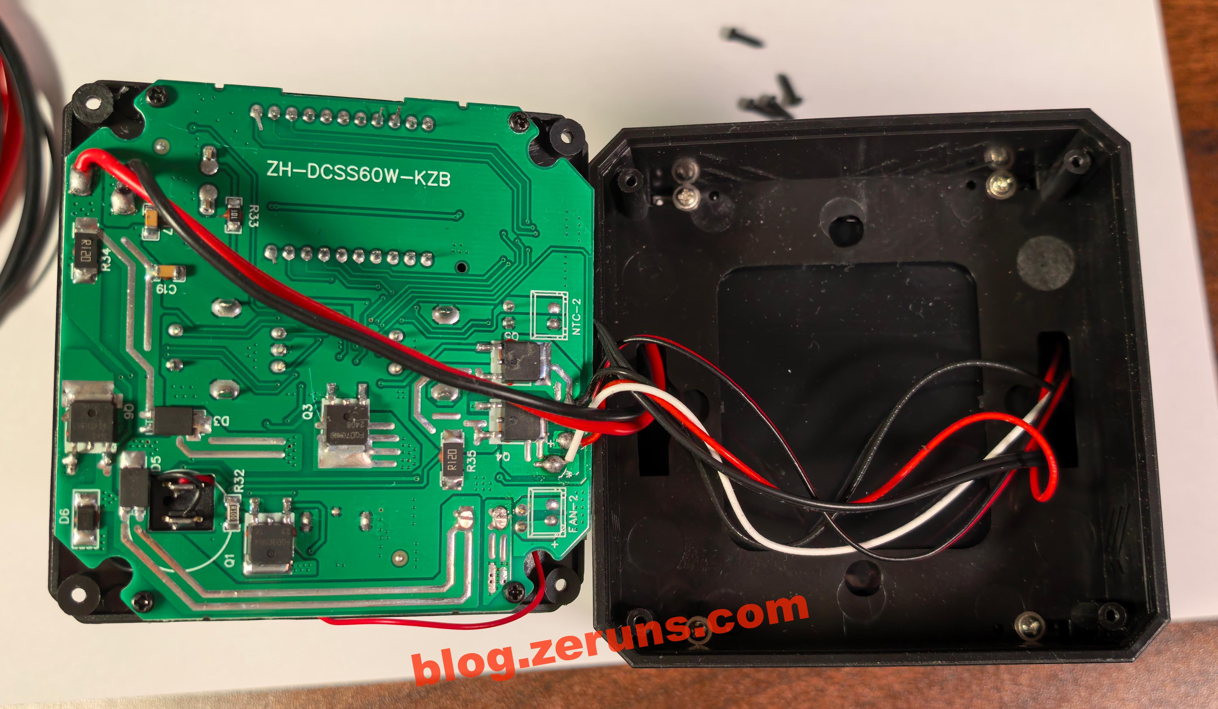
The wire marked with "Y" is the negative for the warm LEDs, "+" is the shared positive for both warm and cool LEDs, and "W" (partially obscured) is the negative for the cool LEDs.
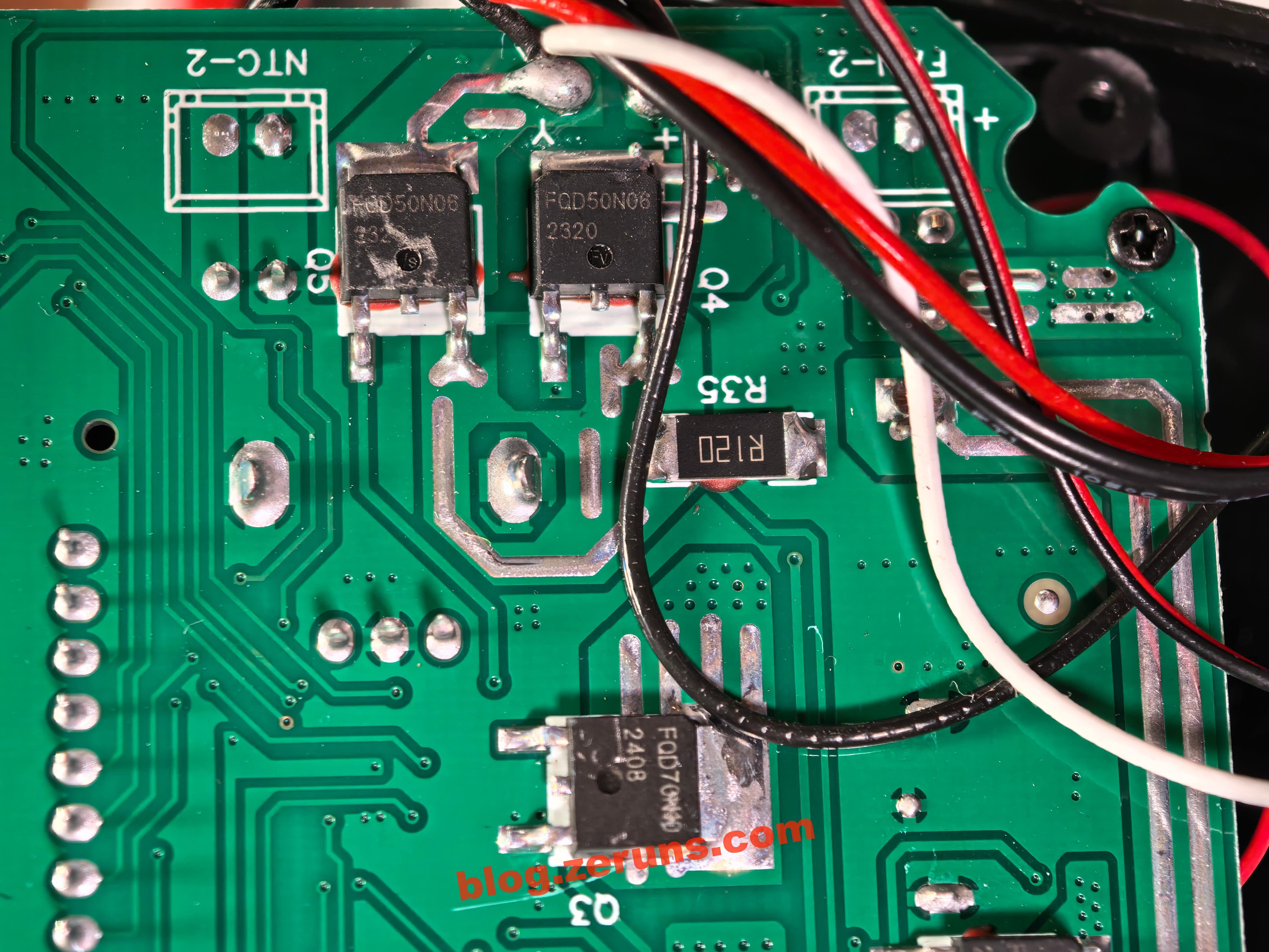
There are two FQD50N06 N-channel MOSFETs (by VBsemi) used to drive the COB LEDs — rated at 60V 58A. These are connected respectively to the warm and cool LED negatives. There's also a 120mΩ resistor nearby, likely used for current sensing.
Below that is a MOSFET labeled Q3, model FQD70N10 (no datasheet found, assumed to be 100V 70A). Based on the PCB traces, it likely serves as the switch for the boost converter powering the LED, with its output connected to the LED positive.
On the right side, there's an NMOS transistor labeled Q1 with the model FQD30N04. Although there's no datasheet available, I estimate its specs to be 40V 30A. Based on the circuit traces, this should be the switching transistor for the Boost converter used for Type-C input.
Below it is a PMOS transistor labeled Q6, model CMD50P06, rated at 60V 50A. Judging from the layout, it appears to be the switching transistor for the Buck converter that steps down the DC input voltage to charge the battery. The 120 mΩ resistor labeled R34 serves as the current sense resistor for the charging circuit.
Next to it are two Schottky diodes, model SB10100L, rated at 100V 10A with a forward voltage drop (VF) of 0.85V. The cathodes of both are connected to the input of the Boost converter for the LED power supply, while their anodes go to the battery's positive terminal and the DC input terminal respectively. There's also a SS56 Schottky diode rated at 60V 5A with VF = 0.7V.
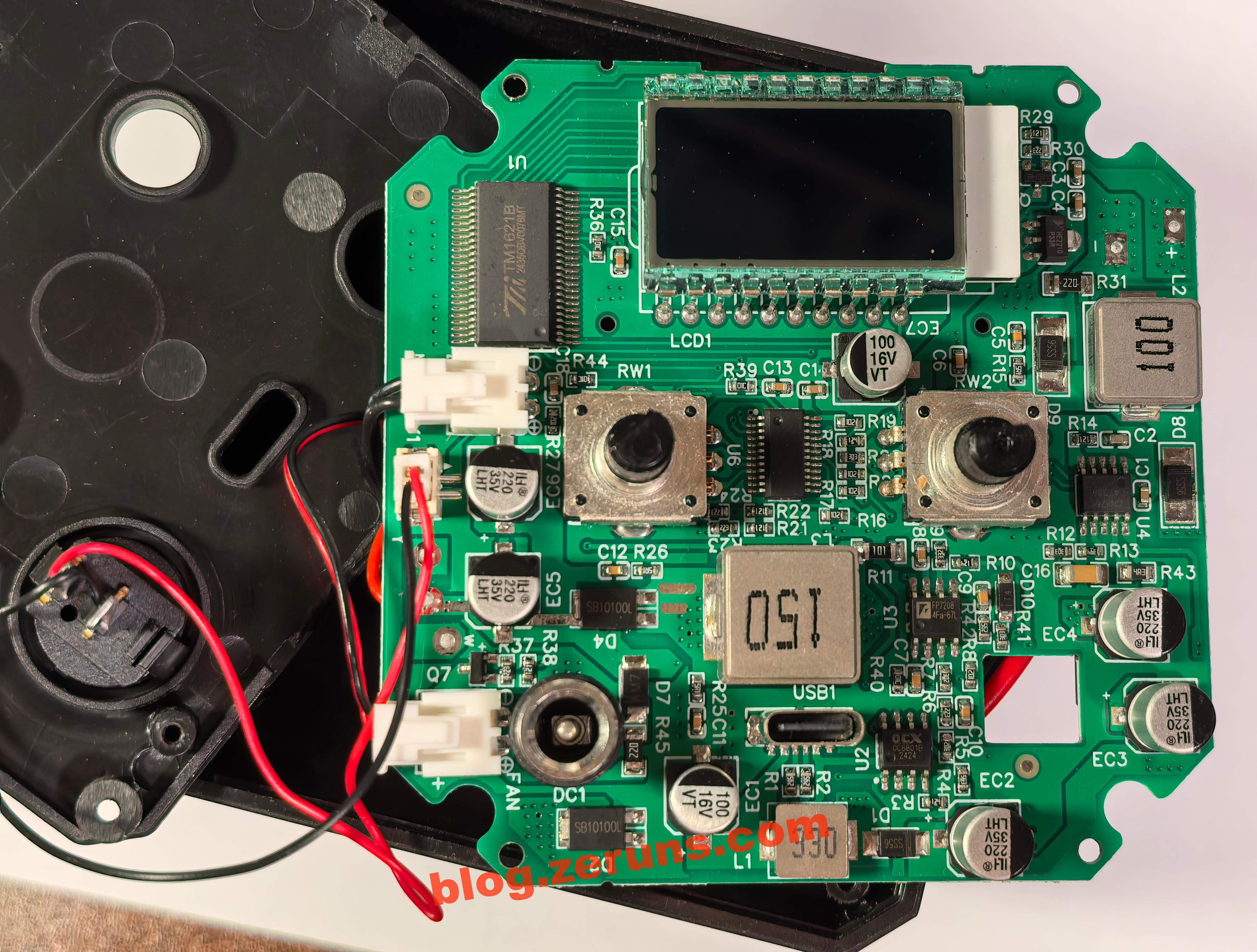
Removing the four screws on the PCB allows access to the front side of the board.
To the left of the LCD is a TM1621B chip, an LCD driver IC. Below it, the two black wires connect to an NTC thermistor socket.
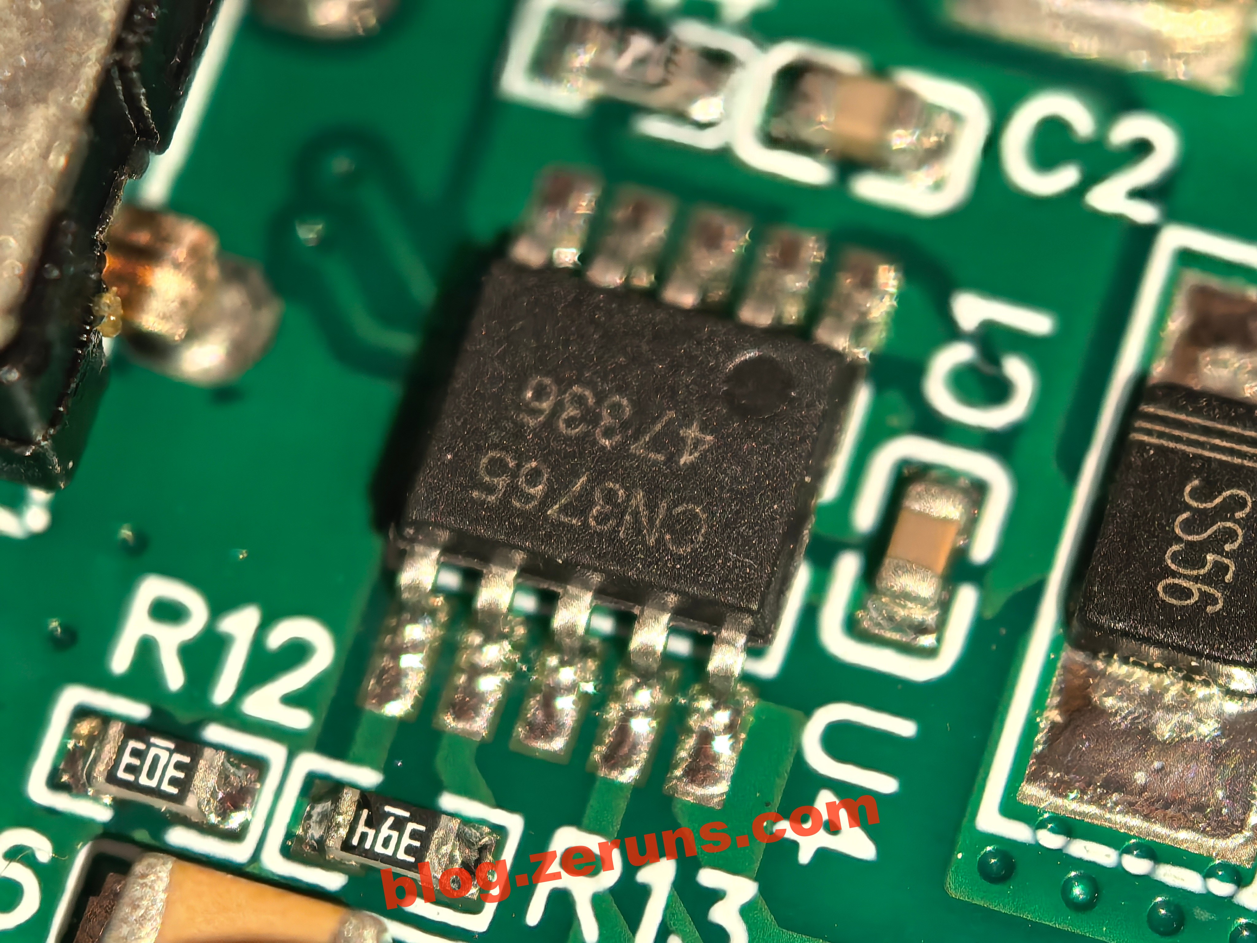
Near the 10μH inductor on the right is a 10-pin IC labeled CN3765, a PWM step-down multi-chemistry battery charger IC supporting trickle, constant current, and constant voltage modes, operating at 310kHz and allowing up to 4A charging current. However, in this design, the input current is below 1A, and the output appears to be around 1A. According to the datasheet, the current sense pin tolerates a max voltage of 120mV, and with a 120 mΩ resistor (R34), the design charging current is 1A. CN3765 manages DC input charging, with Q6 as its switching transistor. Both D8 and D9 are SS56 diodes, where D9 is the freewheeling diode and D8 prevents battery reverse current into the DC jack.
In the center, there's a 24-pin MCU, but its marking has been scratched off, so its model is unknown.
To the right of the 15μH inductor is an 8-pin chip labeled FP7208, a non-synchronous PWM Boost LED driver from Feeling Technology. It operates from 4.5V to 24V at 300kHz and supports DC dimming via a PWM or voltage signal from the MCU. It's a constant-current type driver. The Boost converter consists of FP7208 (controller), Q3 (switch), D4 (diode), EC5 (filter capacitor), and drives the LED's positive terminal. Measured output to GND is 23.5V (at 100% brightness).
To the right of the Type-C port is another 8-pin chip, OC6801B, a DC-DC controller from OCX designed for Boost/Buck-Boost topologies. It supports input voltages from 5V to 40V. In this circuit, it's configured as a Boost controller. Q1 is its switching transistor, D1 is the diode, EC2 is the filter capacitor. A 120kΩ resistor (R3) is connected to pin 4, setting the switching frequency to approximately 211.8kHz based on the datasheet. Its output is connected to the DC input's positive terminal. Measured voltage was 14.4V (at the time of measurement, increases during charging). This is the Boost circuit that raises the Type-C input voltage (from 5V) and feeds it to the DC charging path.
This Type-C connector is 6-pin. Each CC pin is connected to a 5.6kΩ resistor (should have been 5.1kΩ per standard). Without these resistors, PD chargers won't supply power. There's no PD protocol controller on the board, meaning it only supports 5V input. Ironically, adding a PD protocol chip would cost less than 1 RMB, and the Boost converter could then be removed. A 20V PD output could go straight to the DC input and be stepped down to charge the battery, reducing both cost and complexity. Why it wasn’t designed this way is a mystery.
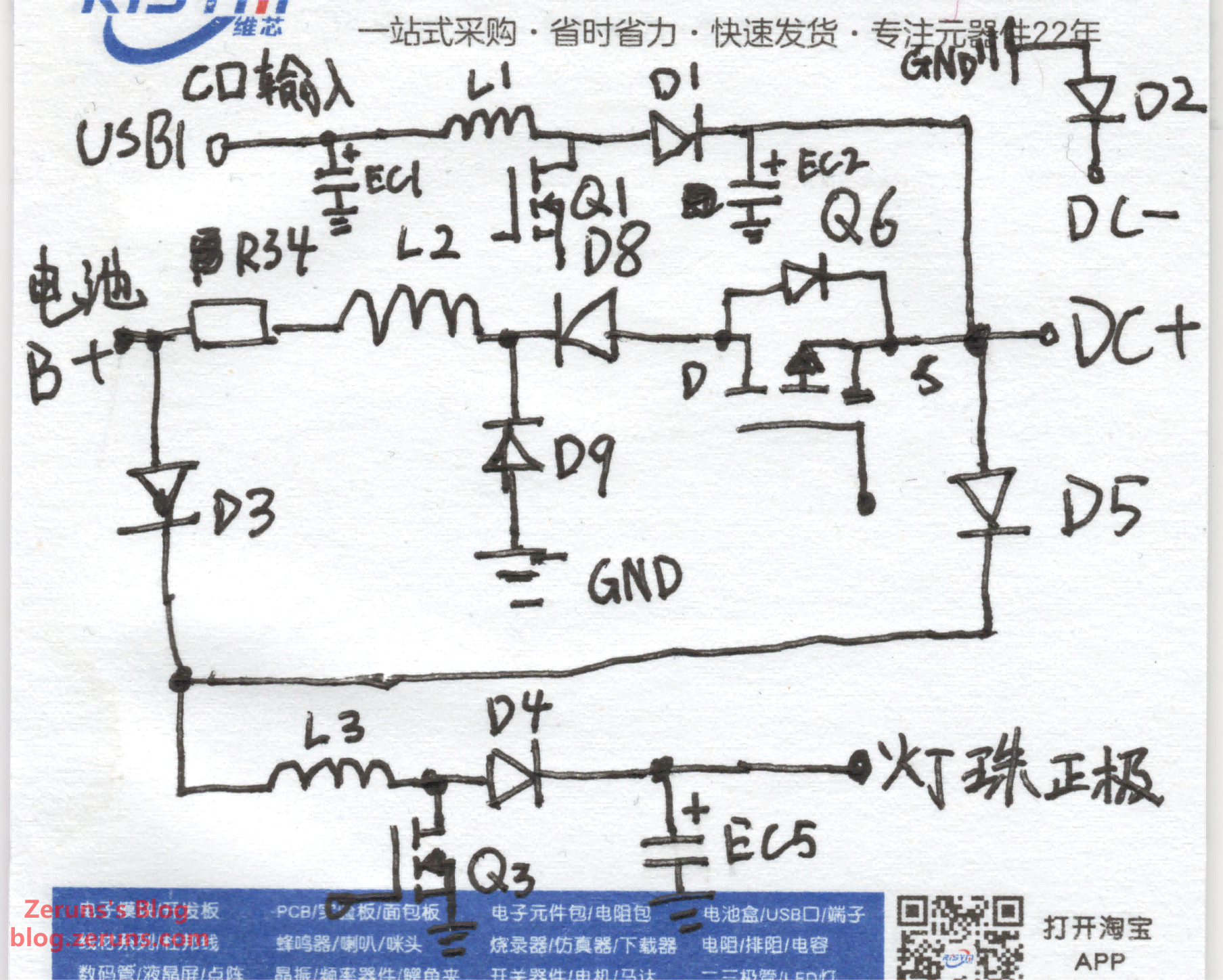
Here's a simplified schematic of the power section. As shown, the Type-C input is Boosted and directly connected to the DC input's positive line. However, the DC jack's negative line is not connected directly to ground—it passes through a diode (D2) to GND, preventing voltage output on the DC jack when only the Type-C input is active.
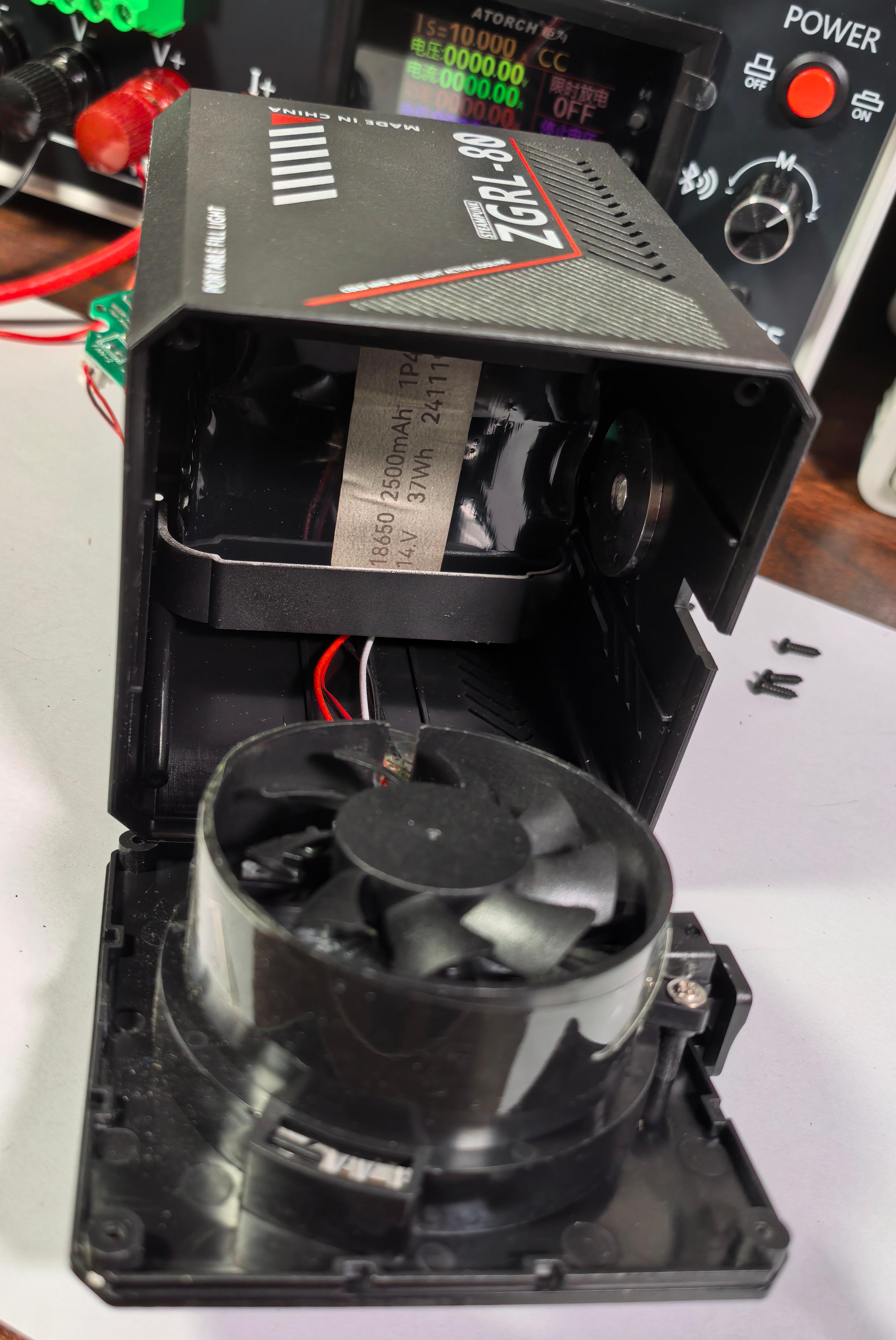
Continuing the teardown, the LED module at the front is mounted on an aluminum heatsink with an attached fan. In the middle of the housing is the battery pack. Based on the sticker, it consists of four 18650 cells in series, rated at 14.8V, 2500mAh, 37Wh, manufactured in November 2024.
That concludes the teardown. Next, let's examine thermal imaging of the circuit in various working conditions.
Thermal Imaging - Heat Analysis
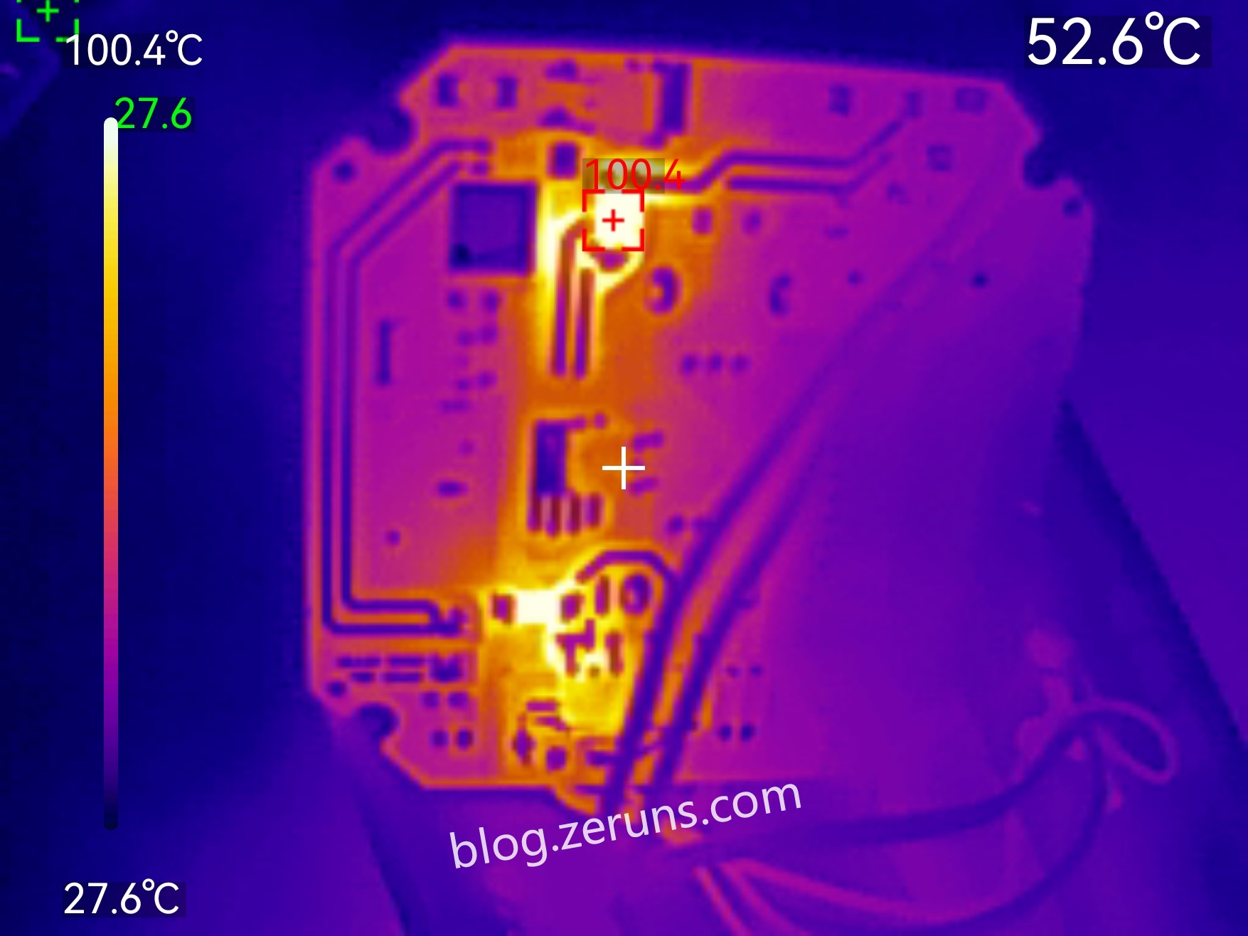
With the light on at 100% brightness and neutral color temperature, powered by the battery, the backside thermal image shows diode D3 reaching over 100°C. The current sense resistor R35 also gets very hot. (Ambient temperature: ~27°C)
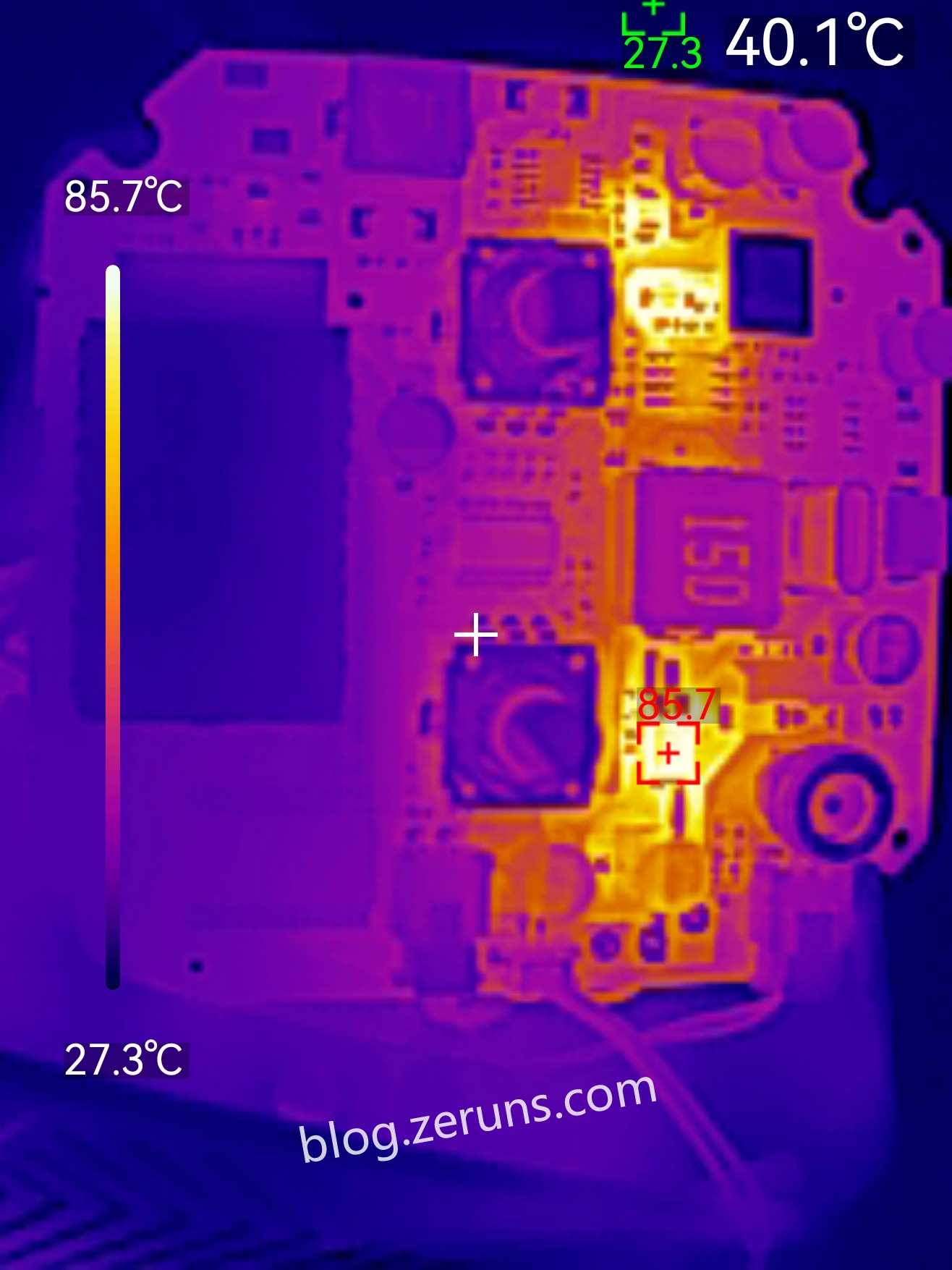
Same conditions, front side thermal image shows D4 reaching over 85°C. (Ambient temperature: ~27°C)
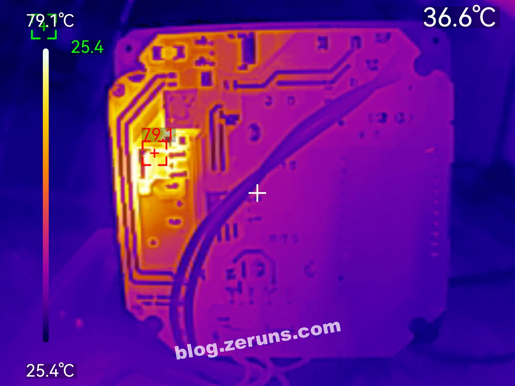
With the light off, charging via Type-C port, the backside image shows Q1 MOSFET reaching 79°C+. (Ambient temperature: ~25°C)
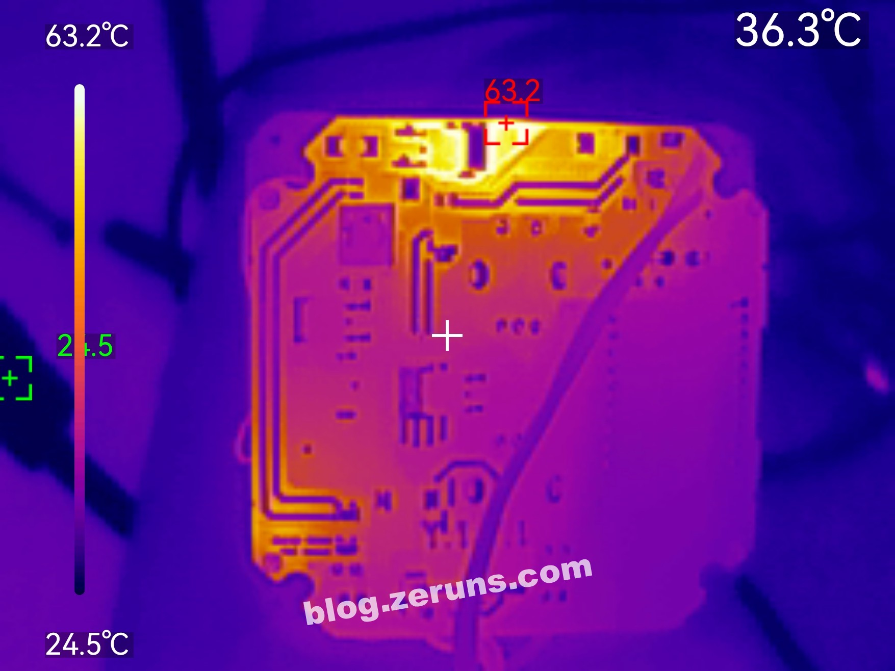
Light off, charging via DC port, backside image shows the hottest point reaching 63°C+, which corresponds to D8. (Ambient temperature: ~25°C)
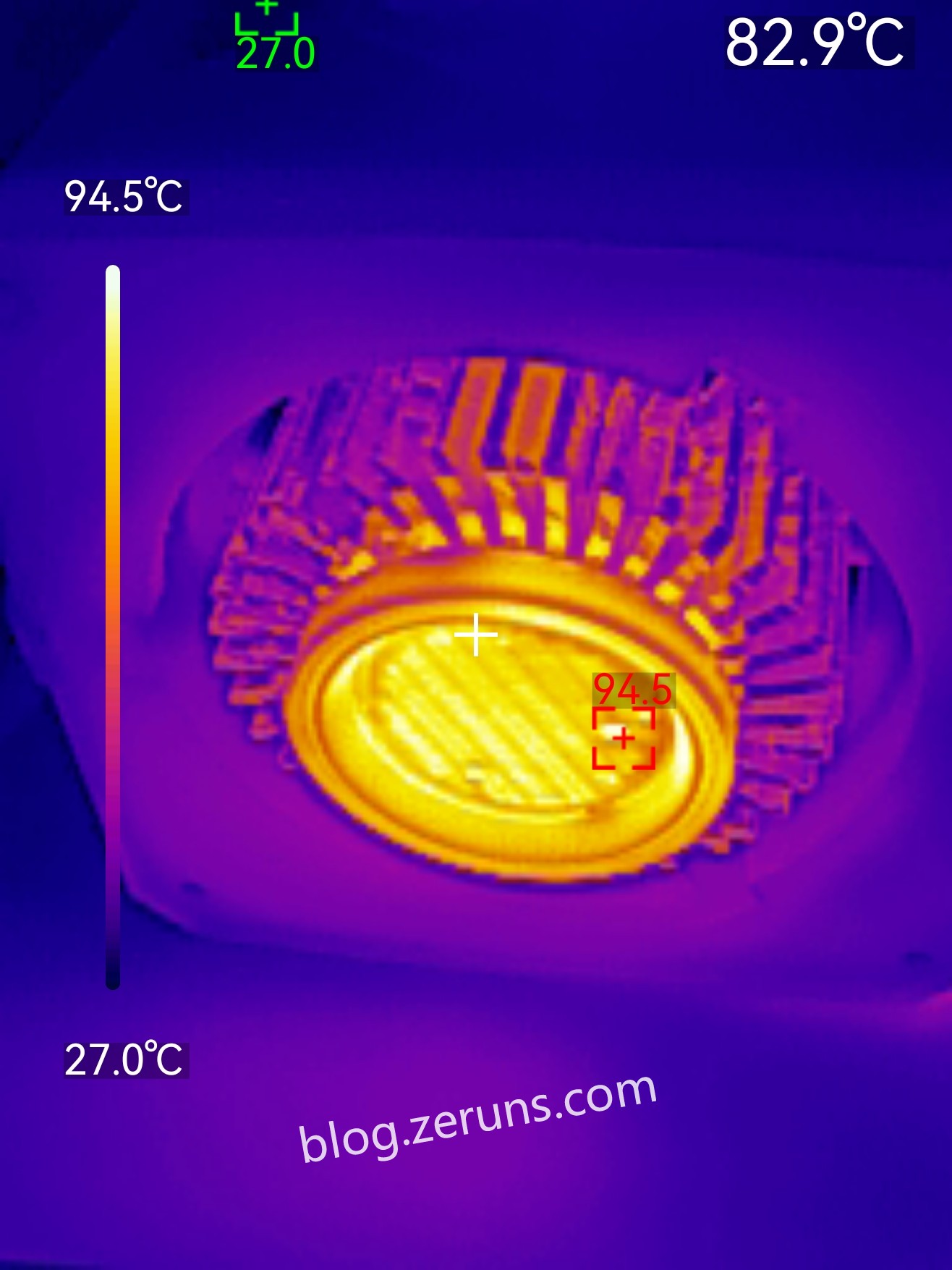
Light on at 100% brightness, neutral color temperature, LED module temperature exceeds 94°C. (Ambient temperature: ~27°C)
Note: Photos were taken at different times, so ambient temperatures vary slightly.
Purchase link for the UTi261M thermal camera: https://u.jd.com/26j0ewm
Recommended Reading
- Affordable and High-Performance VPS/Cloud Hosting Recommendations:https://blog.zeruns.com/archives/383.html
- Minecraft Server Setup Tutorials: https://blog.zeruns.com/tag/mc/
- DIY Small Solar Power Station, 3 Panels Generating 4 kWh/Day: https://blog.zeruns.top/archives/55.html
- Step-by-Step Halo Blog Deployment with 1Panel | Company Website / Personal Blog Setup Guide: https://blog.zeruns.top/archives/47.html
- Tutorial: Deploying a PHP Website on Rainyun RCA Cloud (K8s-based): https://blog.zeruns.top/archives/54.html
- Installing a Coulomb Meter on an E-bike – Step-by-step: https://blog.zeruns.top/archives/60.html


Comment Section