


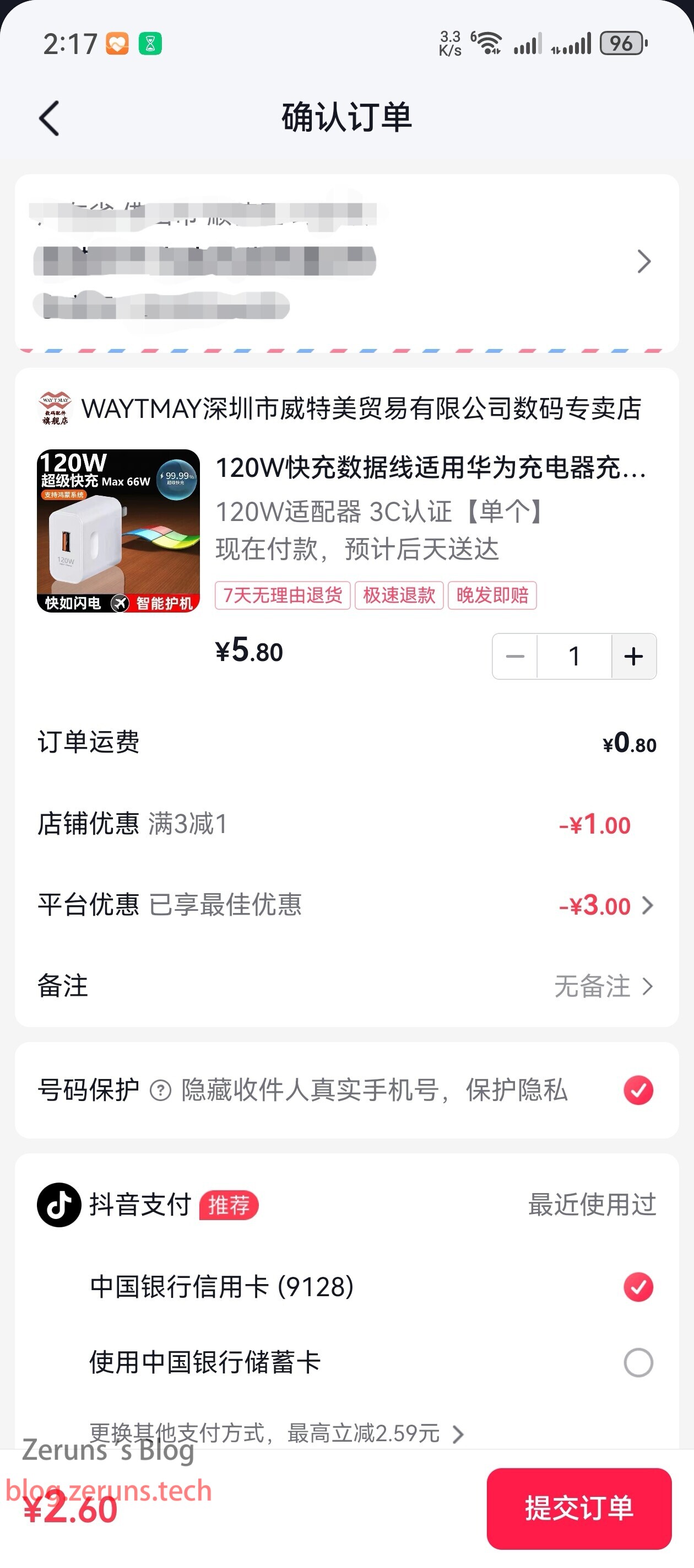
This blog post is about testing and tearing down a 120W fast-charger bought for 2.6 yuan on Douyin Mall.
This charger claims to be compatible with Huawei devices and is designed to look like an official Huawei charger.
Let's take a look at the quality of such a low-cost charger.
Test and teardown video: https://www.bilibili.com/video/BV1kf42127Cu/
Unboxing and teardown review of the Yuli/Torria adjustable power supply X08P3010: https://blog.zeruns.com/archives/698.html
Simple unboxing and review of the Ruideng RD6012P programmable adjustable power supply, a 60V 12A DC power supply with buck and linear voltage reduction: https://blog.zeruns.com/archives/740.html
Purchase link for the official Huawei 100W charger: https://u.jd.com/9sxOBRm
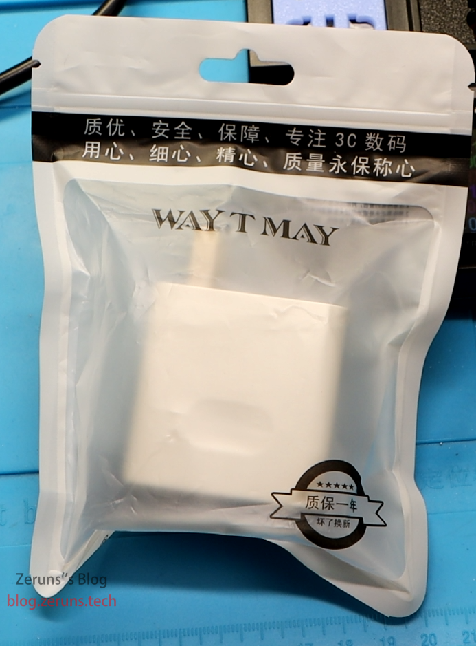
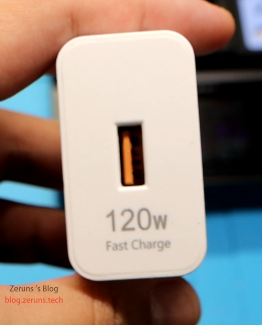
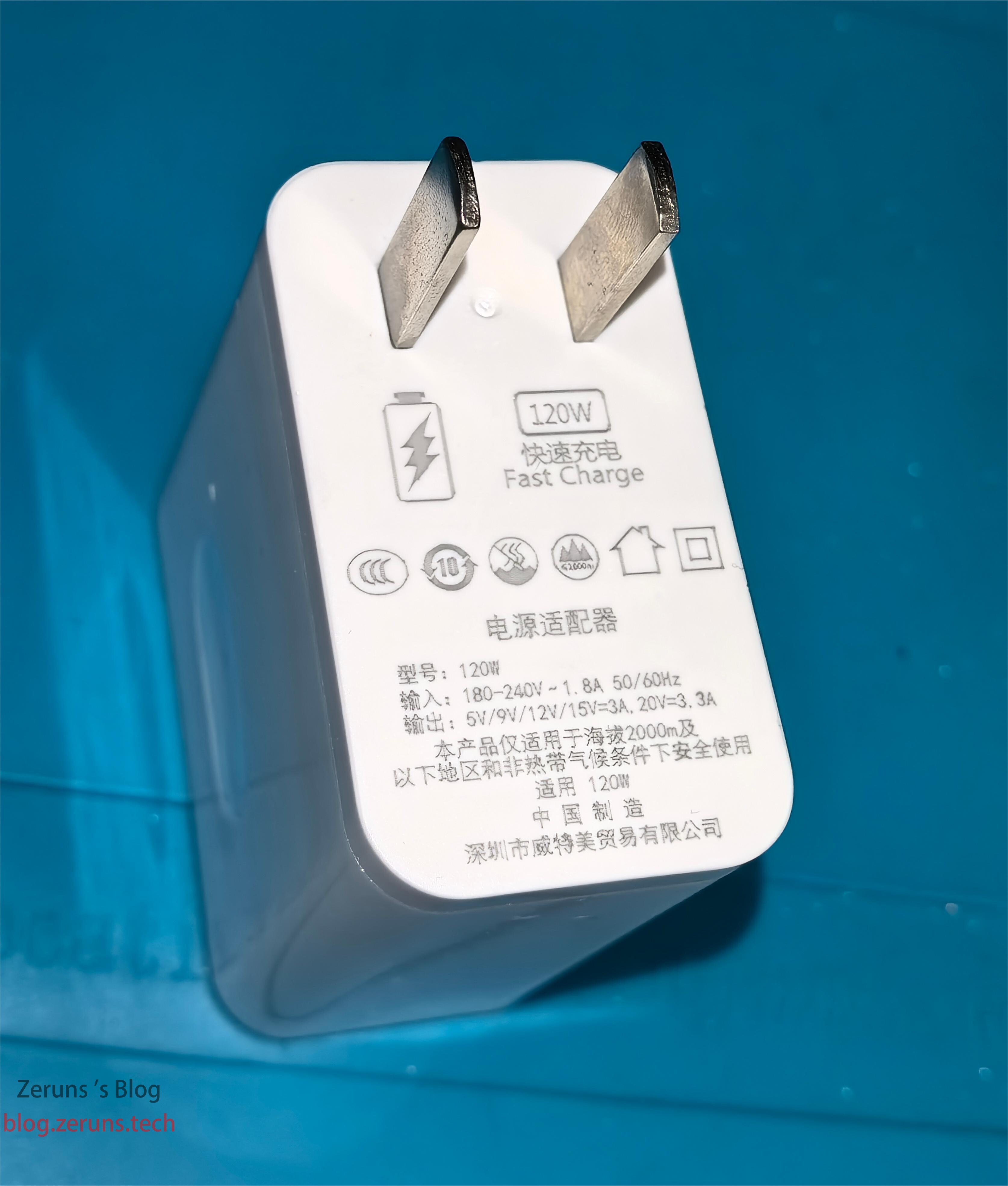
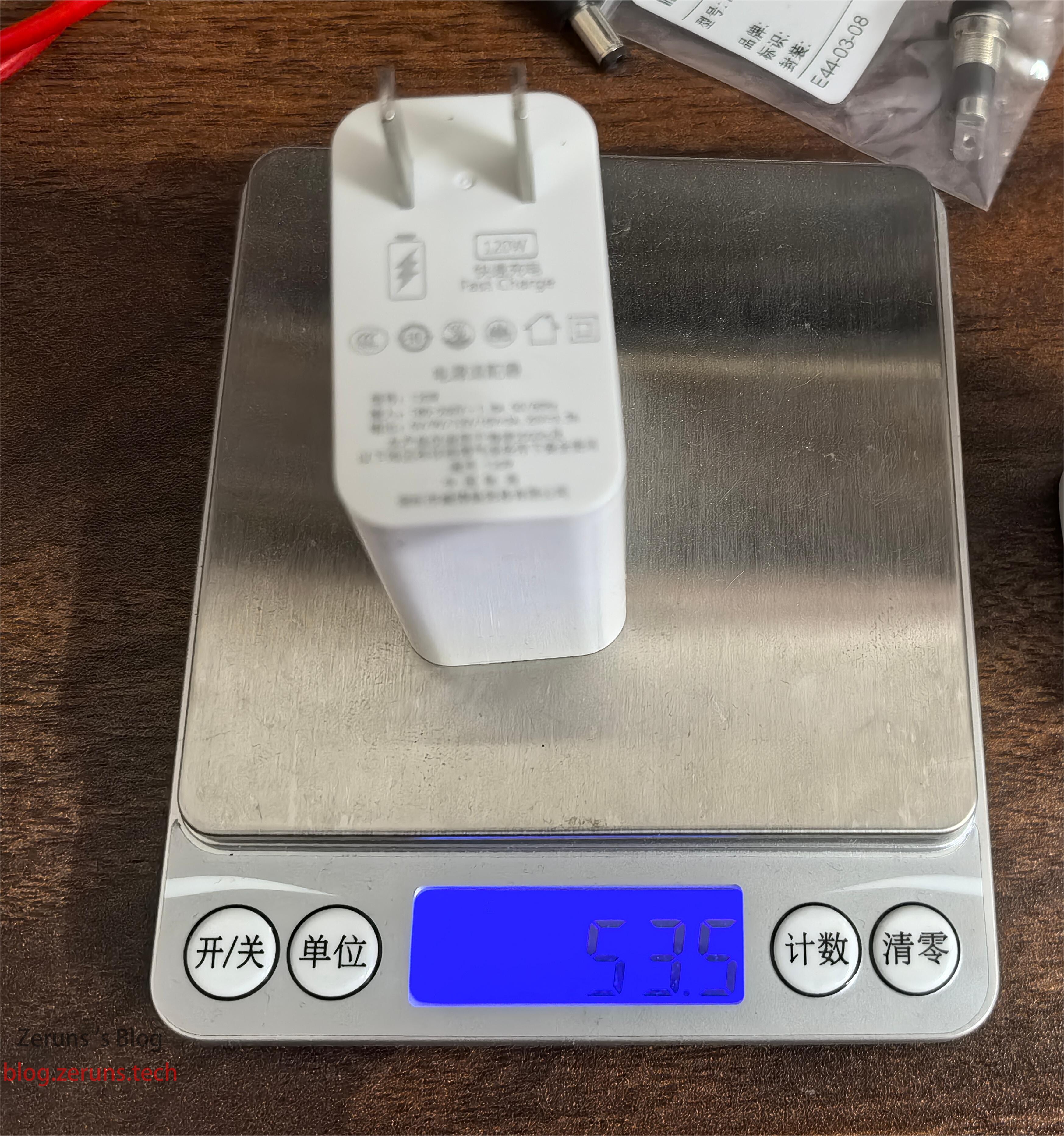
Product Appearance
It has only one USB-A output port, with "120W Fast Charge" written below.
Information printed on the charger:
- Model: 120W
- Input: 180-240V ~ 1.8A 50/60Hz
- Output: 5V/9V/12V/15V=3A, 20V=3.3A
Manufacturer: Shenzhen Vitamei Trading Co., Ltd.
The charger weighs 53.5 grams.
Testing
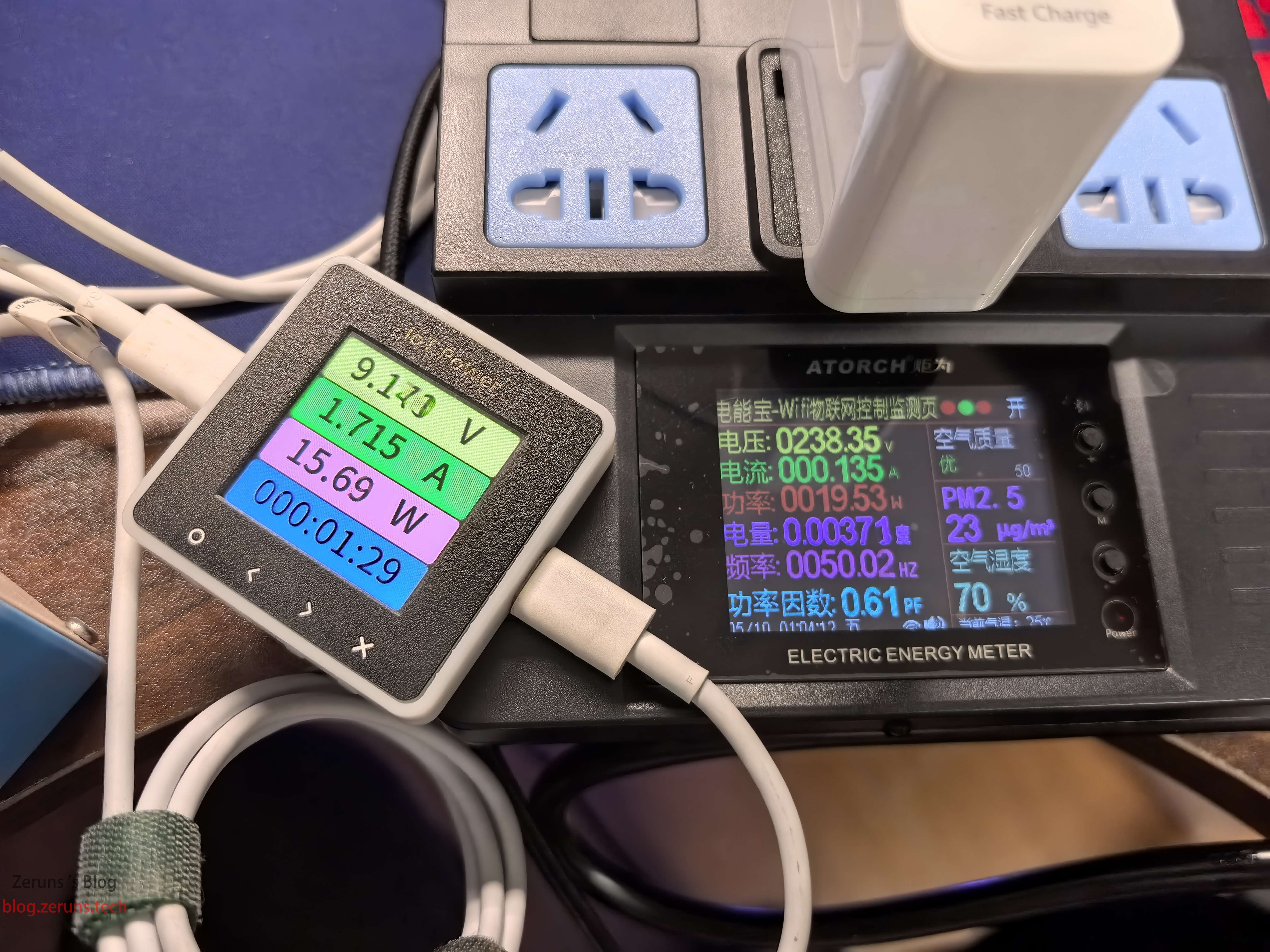
First, let's test the supported fast-charging protocols. There are quite a few, but the maximum output voltage only reaches 12V, not the claimed 20V.

In actual testing, the highest output voltage is 12V, with a maximum output power of 15.6 watts. When fully loaded, the output voltage drops from 12V to 9V, and the charger's conversion efficiency is around 80%.
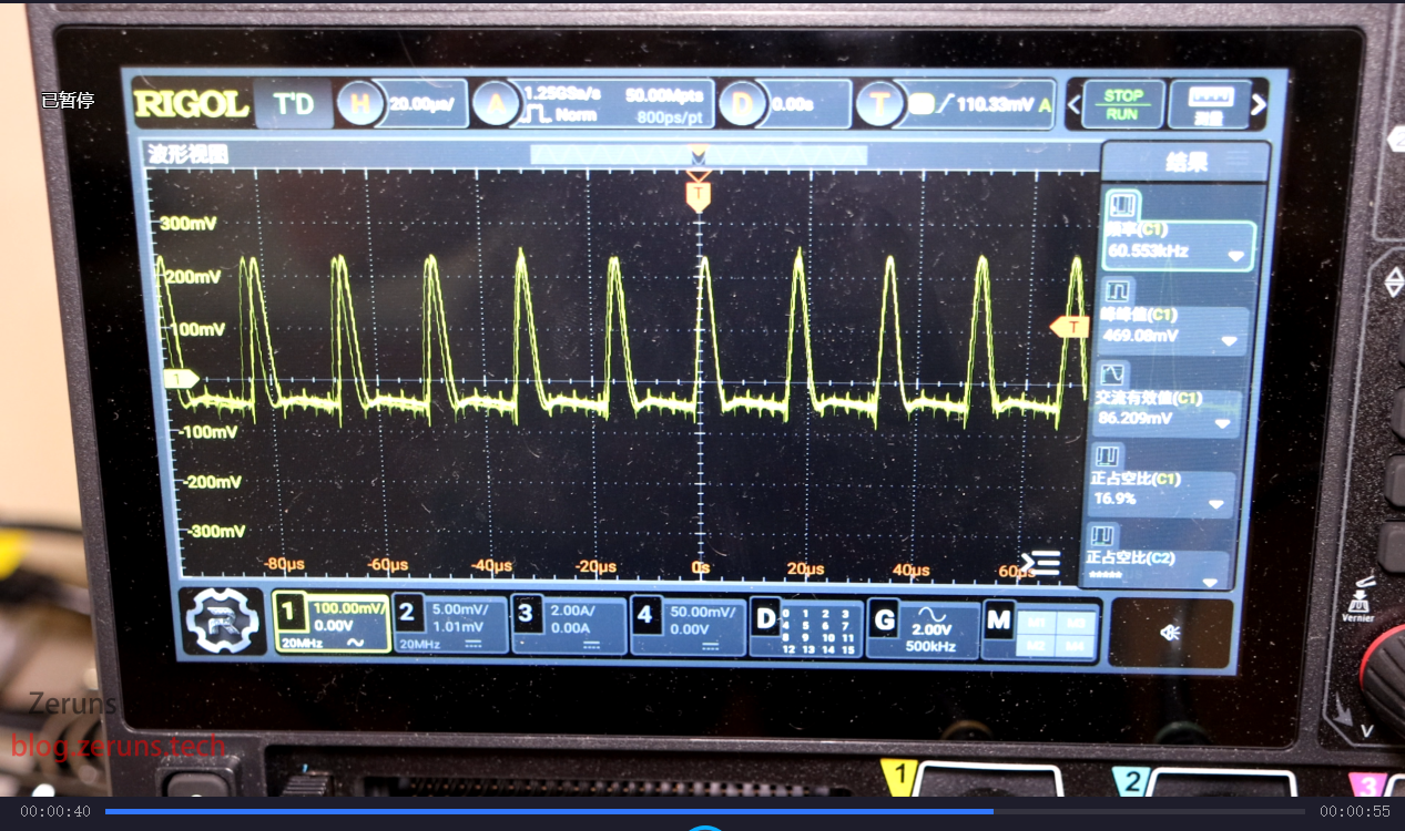
When the charger outputs 12V1A, the peak-to-peak ripple is around 460mV, which is a bit high.
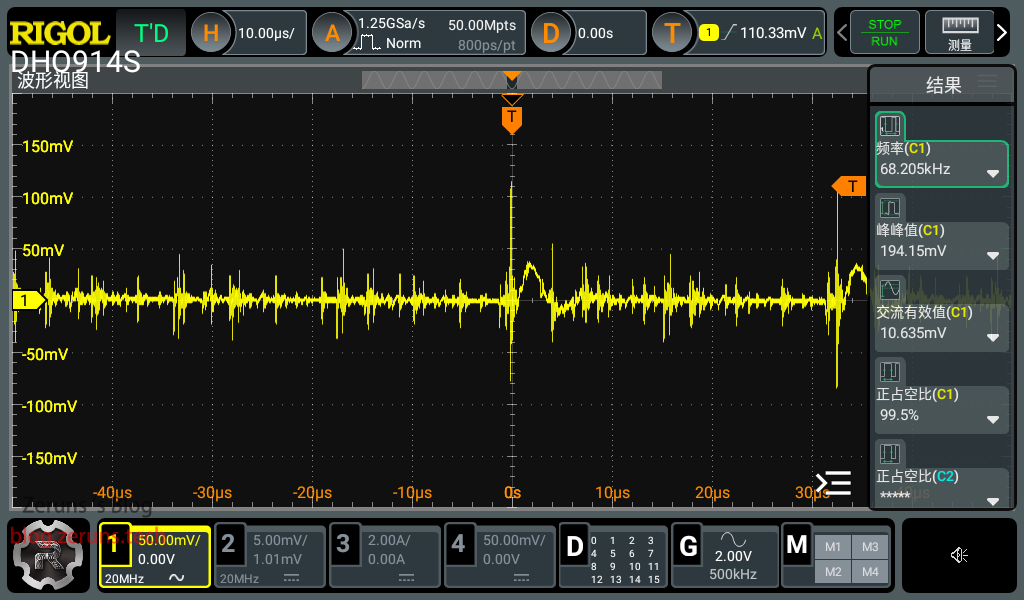
The ripple when the 5V output is no-load is shown in the figure below, with a peak-to-peak ripple of about one hundred millivolts.
Teardown
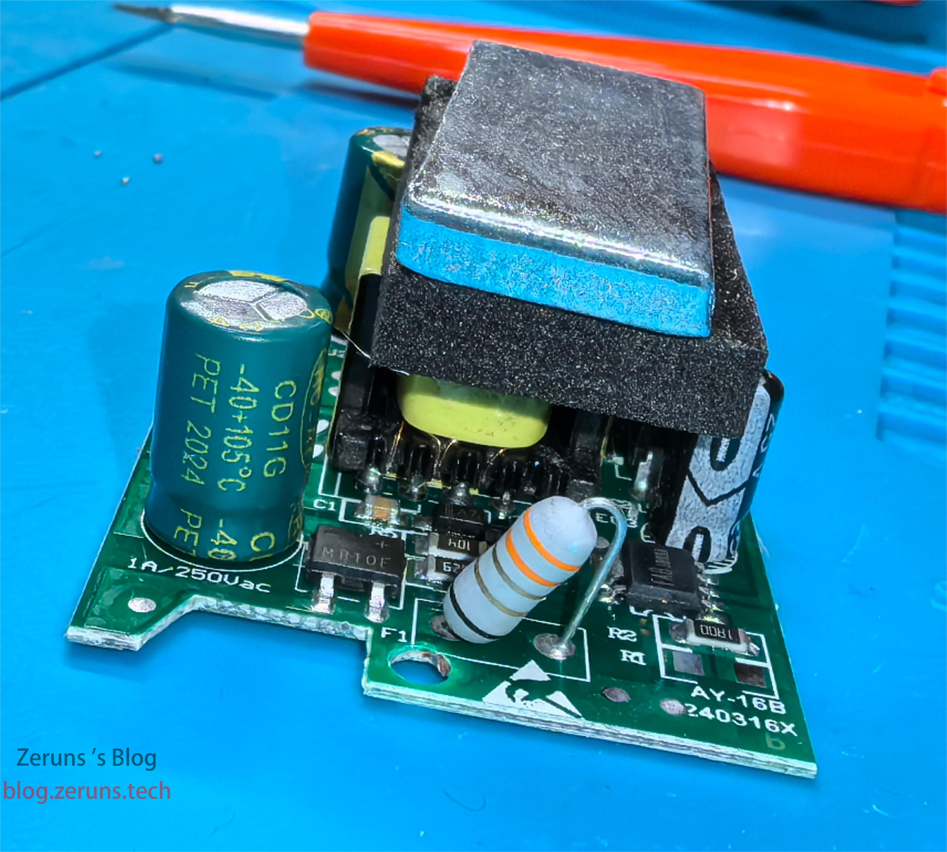
Removing the top cover.
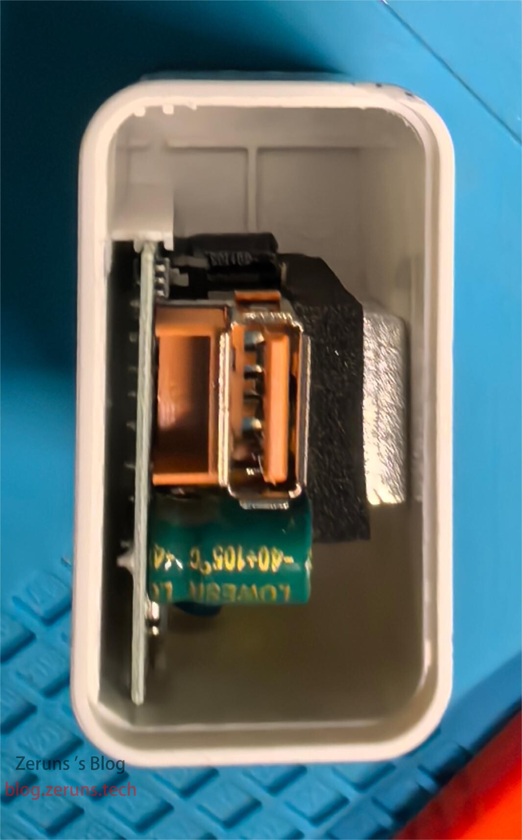
Taking out the circuit board, there is a weight block on the transformer. This power supply is likely a flyback switch-mode power supply.
Removing the weight block.
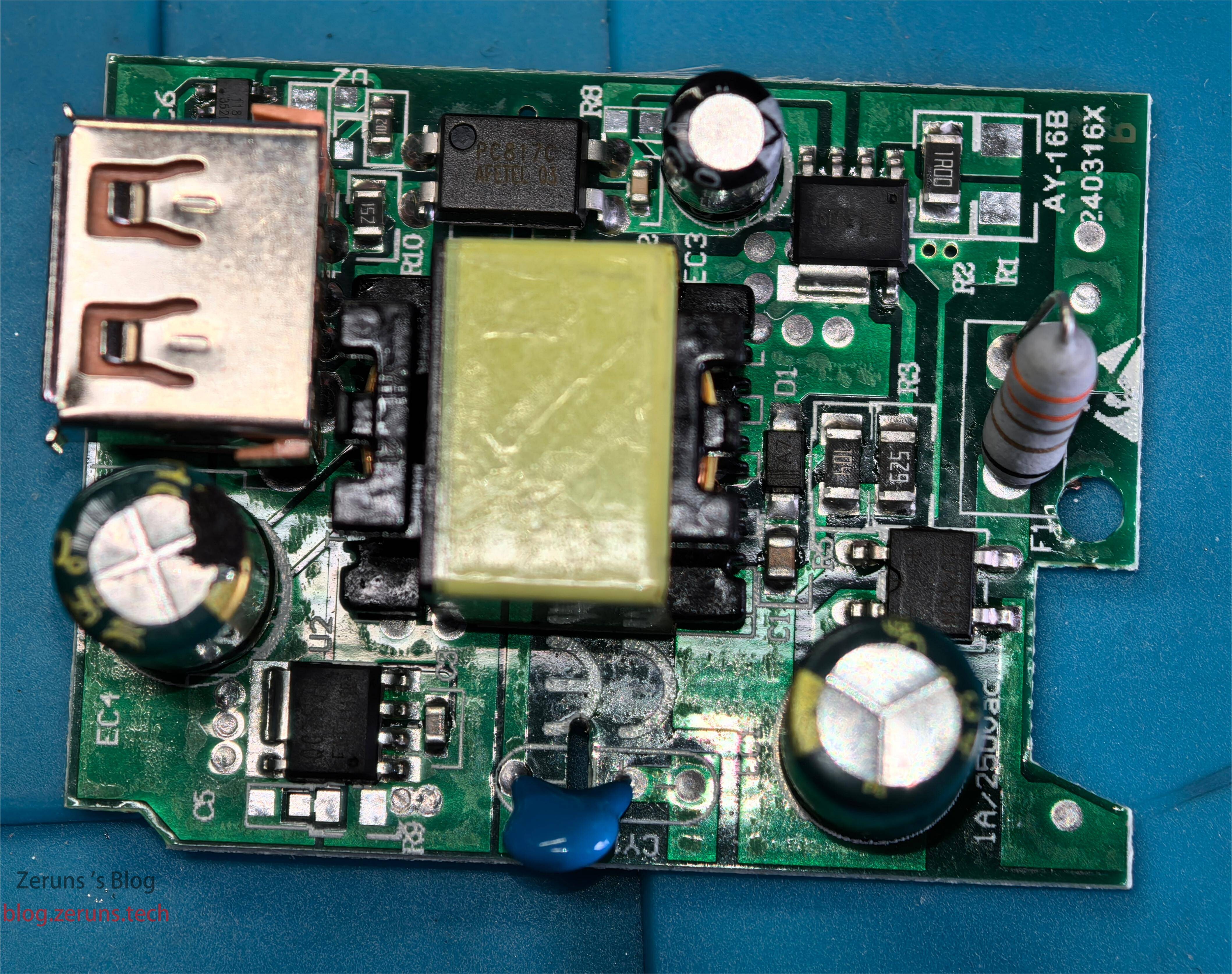
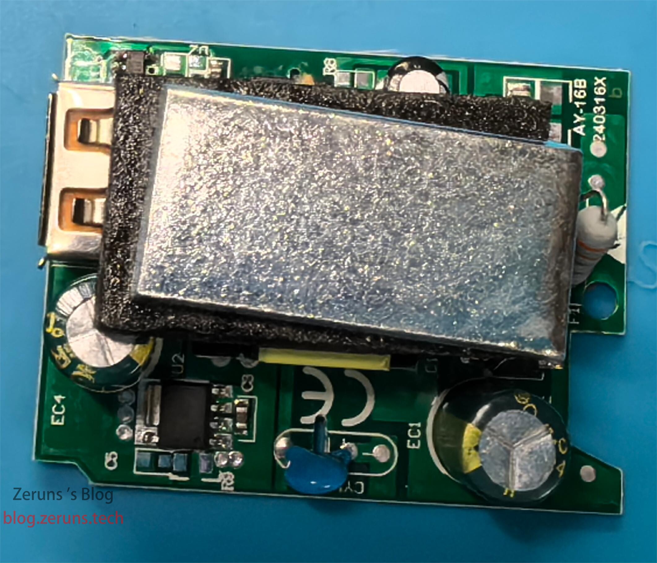
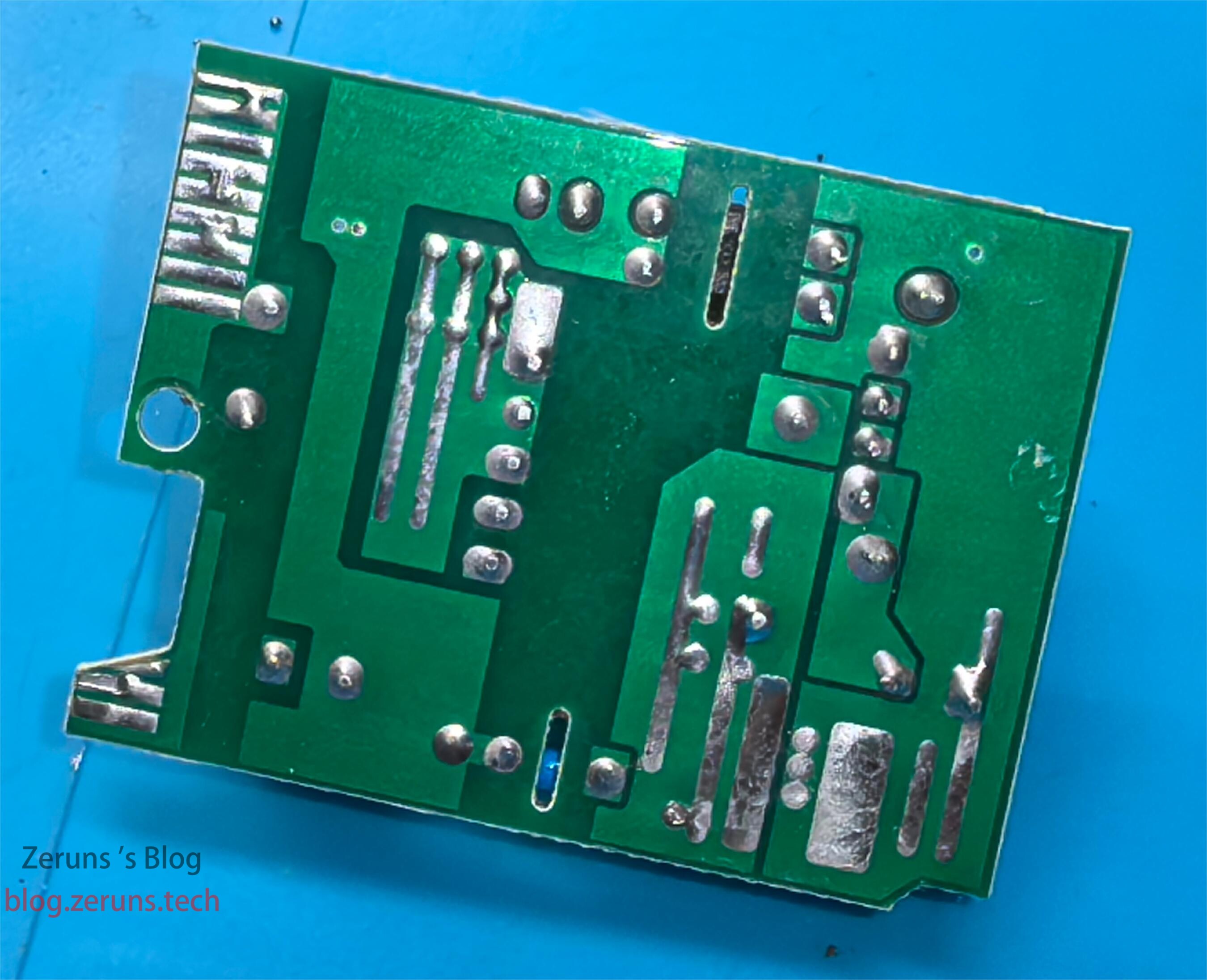
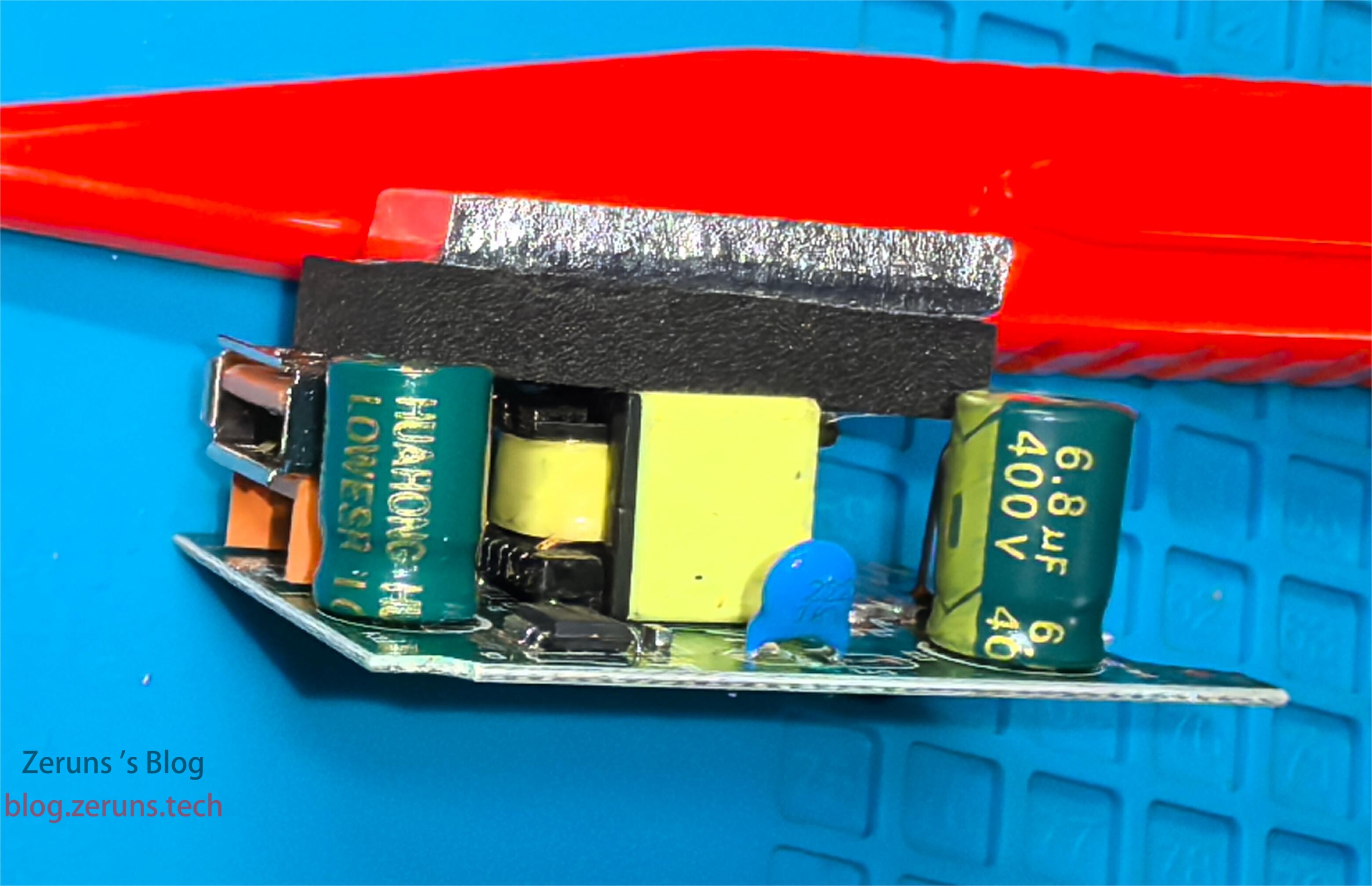
The bottom side of the PCB.
On the side, the AC input side filter capacitor is 400V 6.8μF, which is a bit small. The Y capacitor is 2.2nF.
The output side filter capacitor is blocked by the USB interface, only showing a voltage rating of 16V. The capacitance value is not visible, but it was measured with a multimeter to be 644μF.
A carbon film resistor is connected in series before the rectifier bridge at the AC input end, acting as a current-limiting resistor.
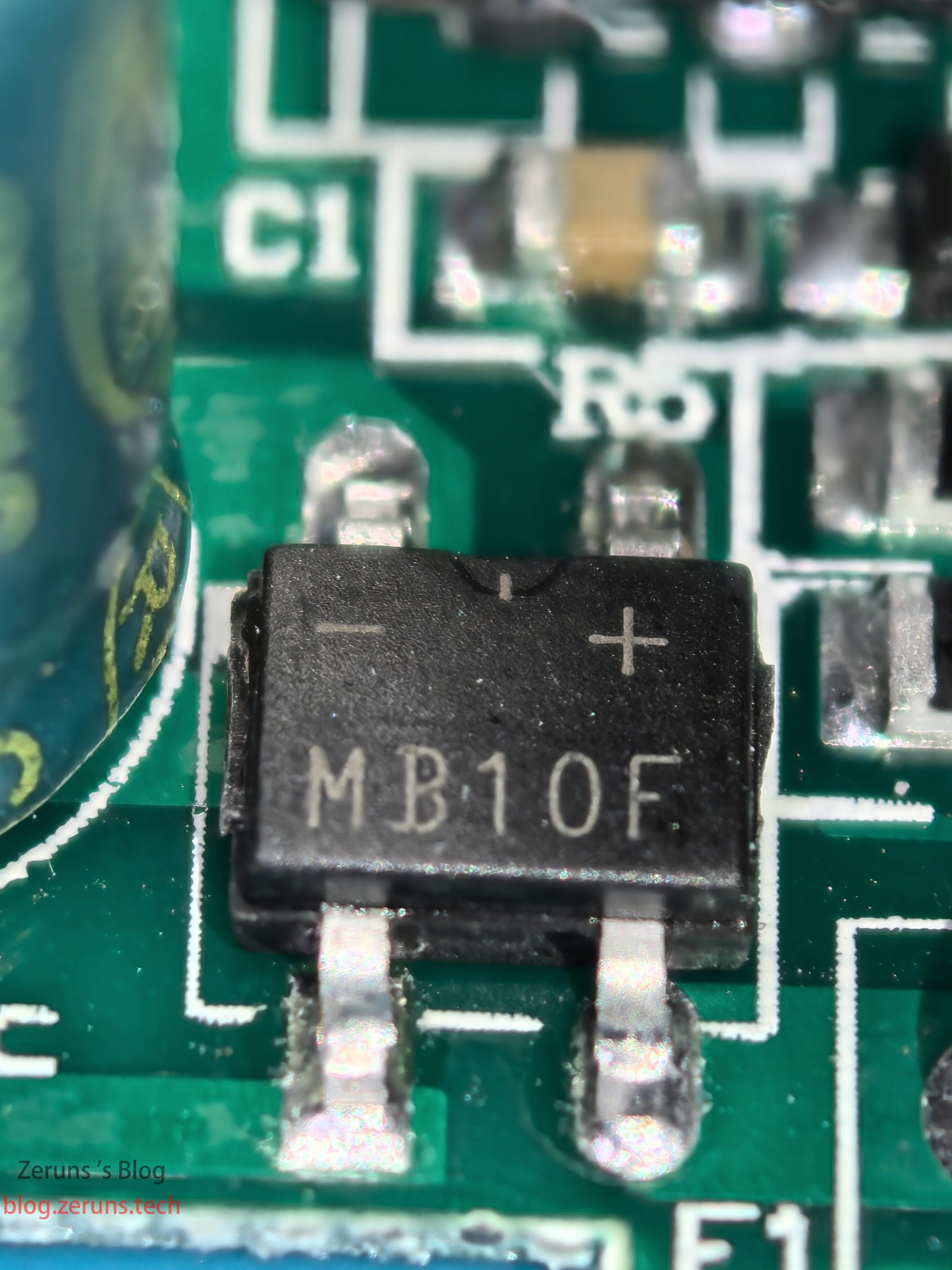
The rectifier bridge model is MB10F, with performance parameters of 1000V/1A.
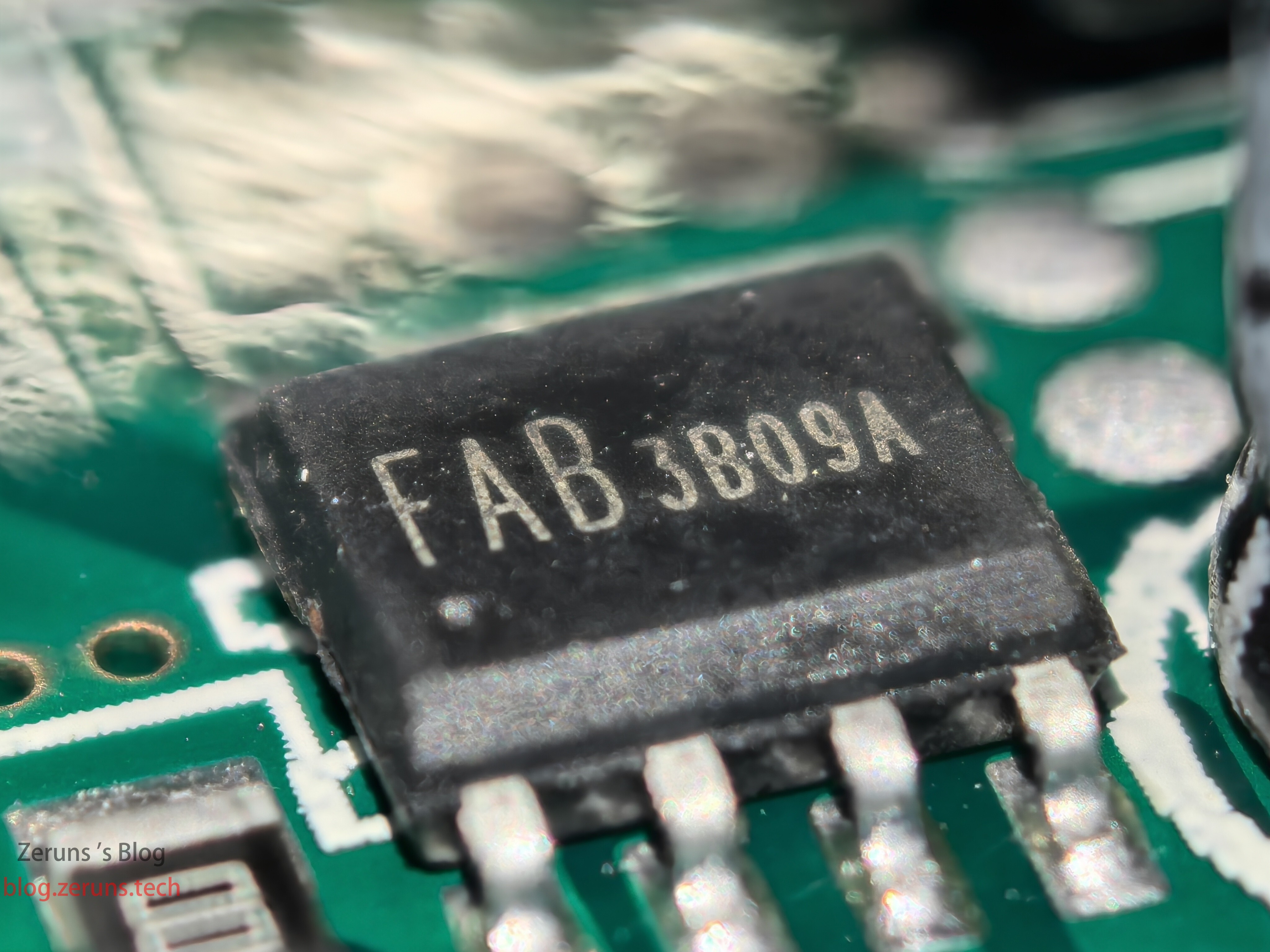
The power chip on the primary side of the high-frequency transformer is model FAB3B09A, and no information could be found about it.
Pin 2 of the chip is connected to the negative pole of the rectifier bridge through a 1Ω resistor, which is likely a current-sensing resistor used to detect current. Reducing the resistance value could increase the output power, but it would not be safe.
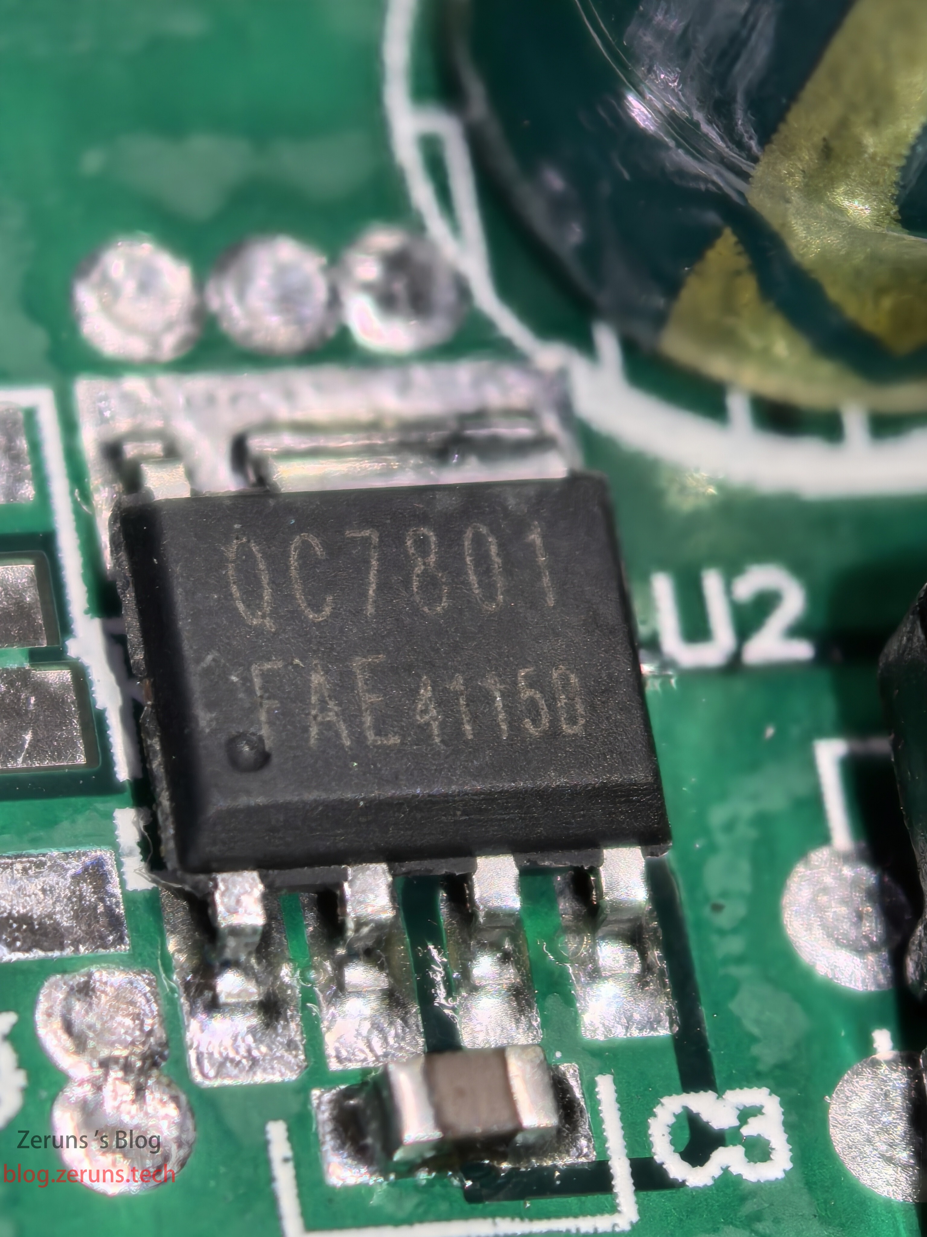
There is a chip labeled QC7801/FAE41150 on the output side, which also couldn't be found in any information, likely a MOSFET.
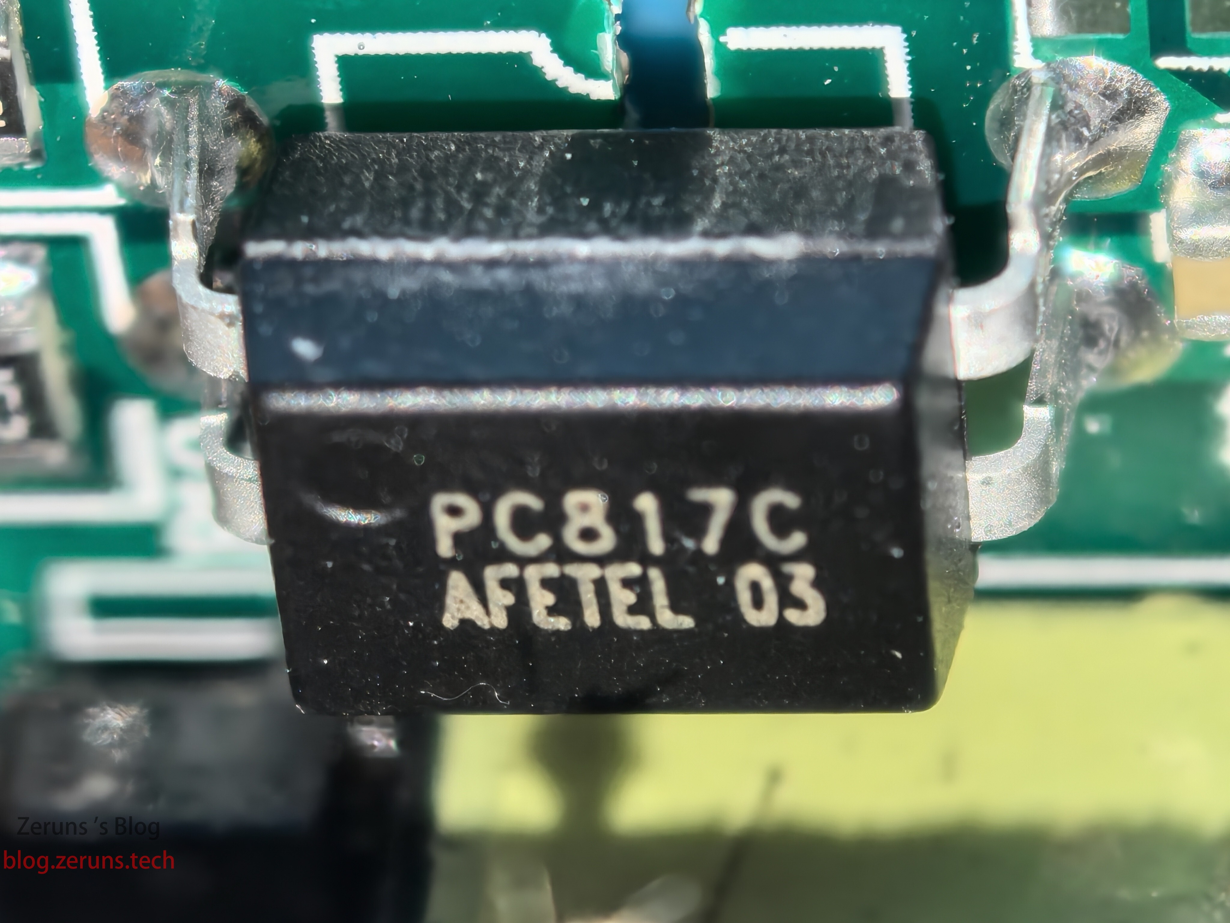
The optocoupler model is PC817C.
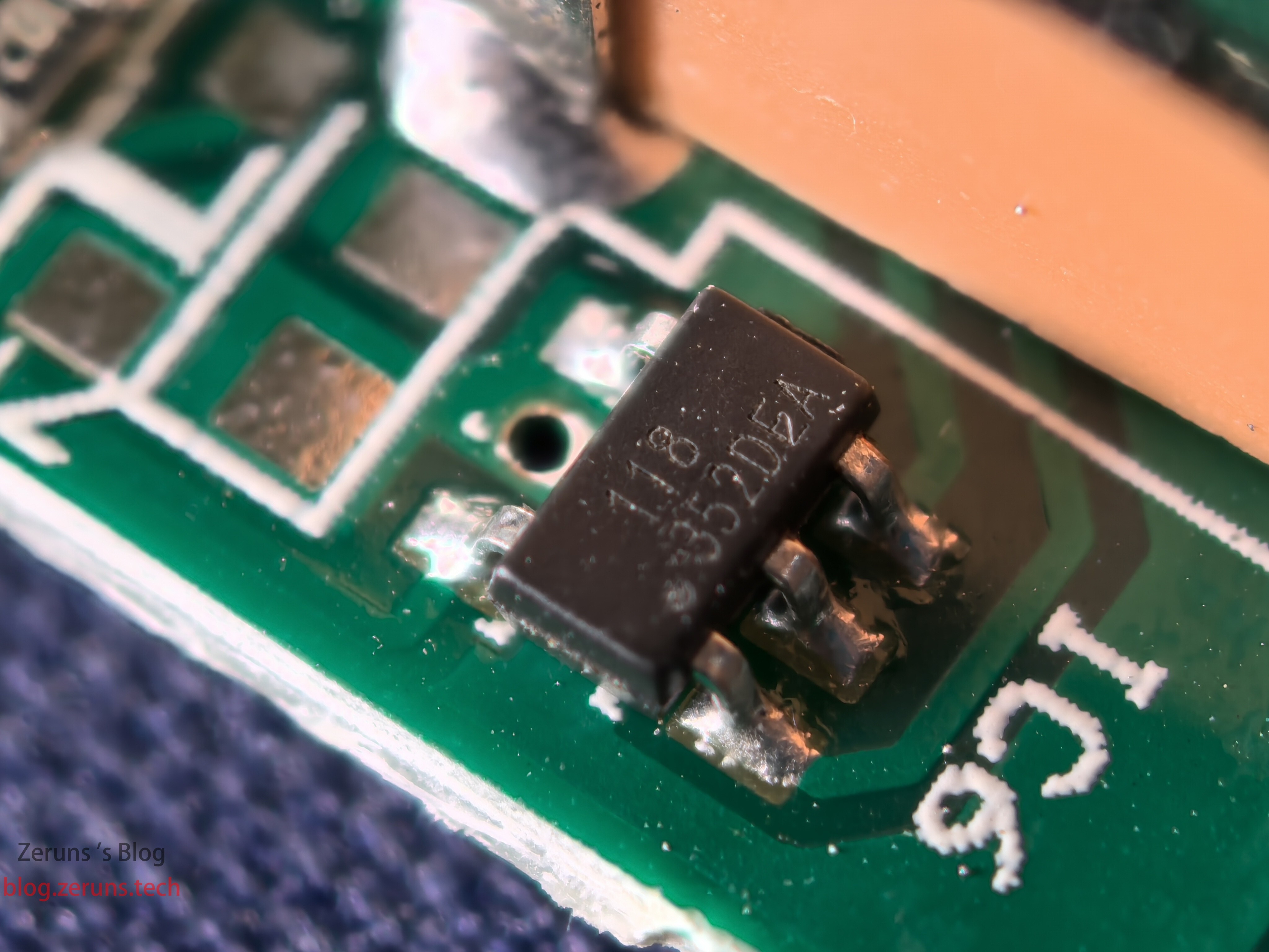
The small 6-pin chip next to the USB interface is likely a fast-charging protocol chip, model 118/352DEA, and no information could be found about it.
It is not recommended to buy this kind of power supply, as the components used are too poor, and the performance is severely misrepresented.
Recommended Reading
- Highly cost-effective and cheap VPS/cloud server recommendations: https://blog.zeruns.com/archives/383.html
- My World server setup tutorial: https://blog.zeruns.com/tag/mc/
- Build a blog website without coding! Super detailed personal blog setup tutorial: https://blog.zeruns.com/archives/783.html
- Tutorial for setting up and using an internal network penetration server, NPS setup and usage tutorial: https://blog.zeruns.com/archives/741.html
- Tutorial for setting up a RainCloud GPU cloud server with SD (Stable Diffusion), to build your own AI painting website: https://blog.zeruns.com/archives/768.html
- Open-source intelligent electronic load based on CH32V307, embedded competition project open-source: https://blog.zeruns.com/archives/785.html


Comment Section