


Teardown analysis of the LADS D1500 Uninterruptible Power Supply (UPS).
The UPS used in my home network cabinet broke down. It seemed that the battery could no longer hold a charge. When the mains power was cut off, there was no output. However, when the load was disconnected, it could still output power for a short period of time on its own, indicating that the battery was likely the issue. Unfortunately, the UPS had just passed its one-year warranty period when I discovered the problem. I have purchased two LADS UPS units in the past, and the other one, bought even earlier, also experienced a significant reduction in battery life, dropping to less than 5 minutes of runtime. Luckily, I noticed this issue one month before the warranty expired and was able to request a replacement on JD.com. It seems that the batteries in LADS UPS units degrade rather quickly.
Teardown video: https://www.bilibili.com/video/BV1dy411b77e/
Test and teardown of a 120W charger from Douyin Mall priced at 2.6 yuan: https://blog.zeruns.com/archives/786.html
Specifications
- Model: D1500
- Capacity: 1500VA/900W
- Input Voltage Range: 145~290VAC
- Power Factor: ≥0.99 @ rated voltage (100% load)
- Output Voltage Range (Mains Mode): 195~255VAC
- Output Frequency Range (Battery Mode): 50Hz ± 0.5Hz
- Output Waveform (Battery Mode): Square Wave
- Transfer Time: ≤10ms
- Battery Model: 12V/9AH
- Number of Batteries: 2
- Charging Time: 10 hours~16 hours
- Dimensions: Length x Width x Height 320120190mm
- Weight: 11kg
Purchase Links:
- LADIS D1500: https://u.jd.com/xsJjvIr
- Schneider BK650M2: https://u.jd.com/xiJZA8x
- Huawei 1KTTS-1KVA/800W: https://u.jd.com/xqJoSOJ
Disassembly
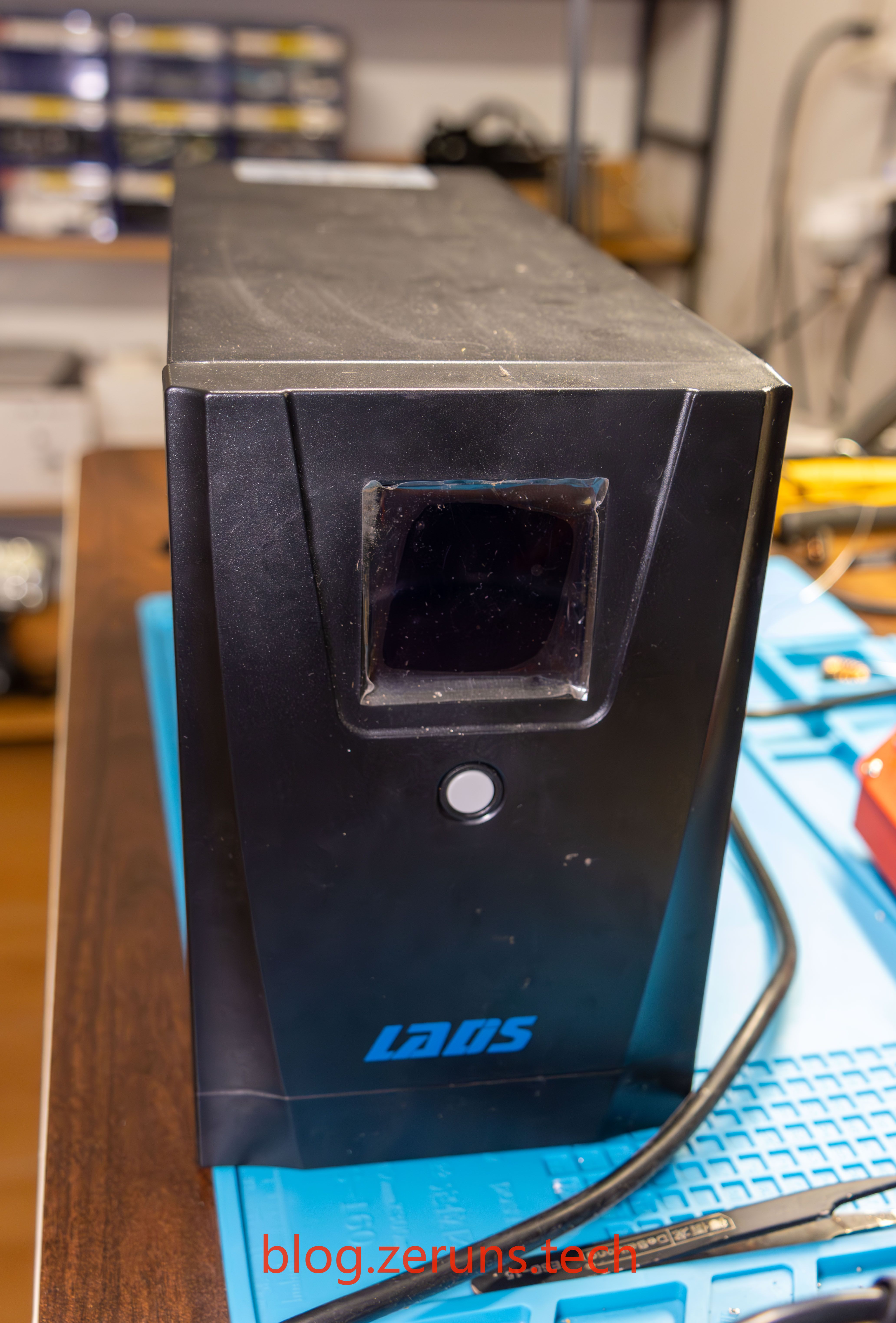
Front
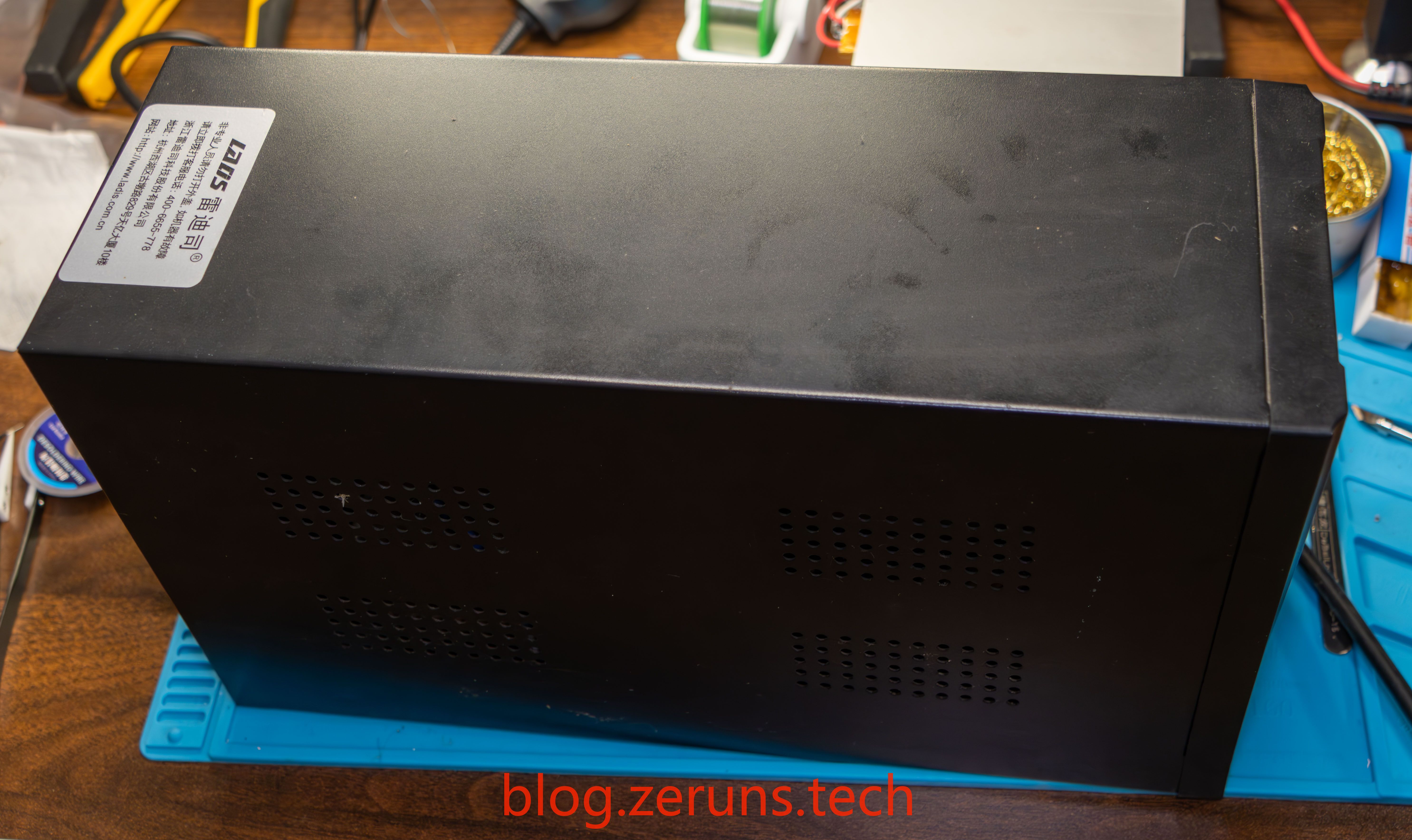
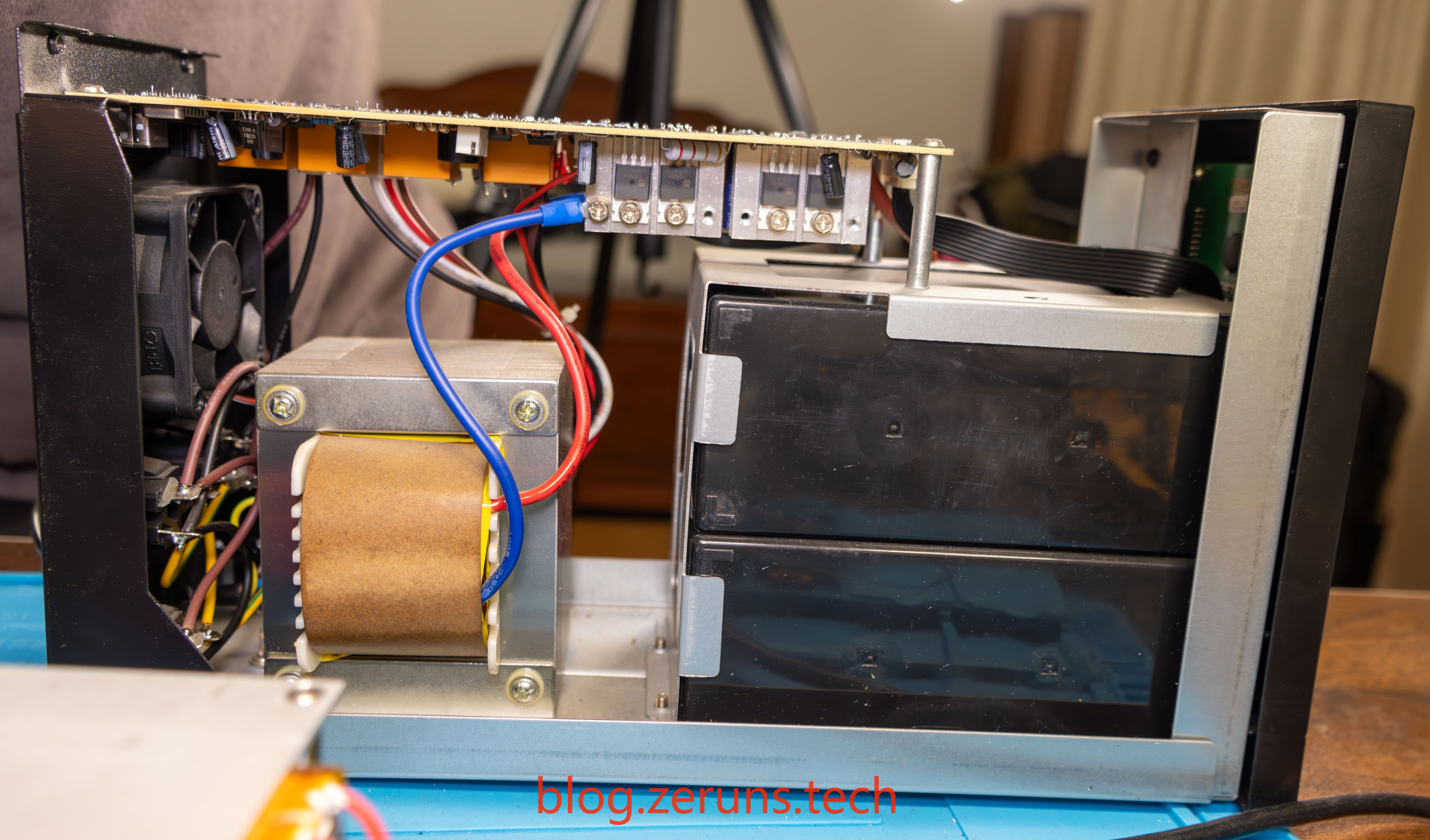
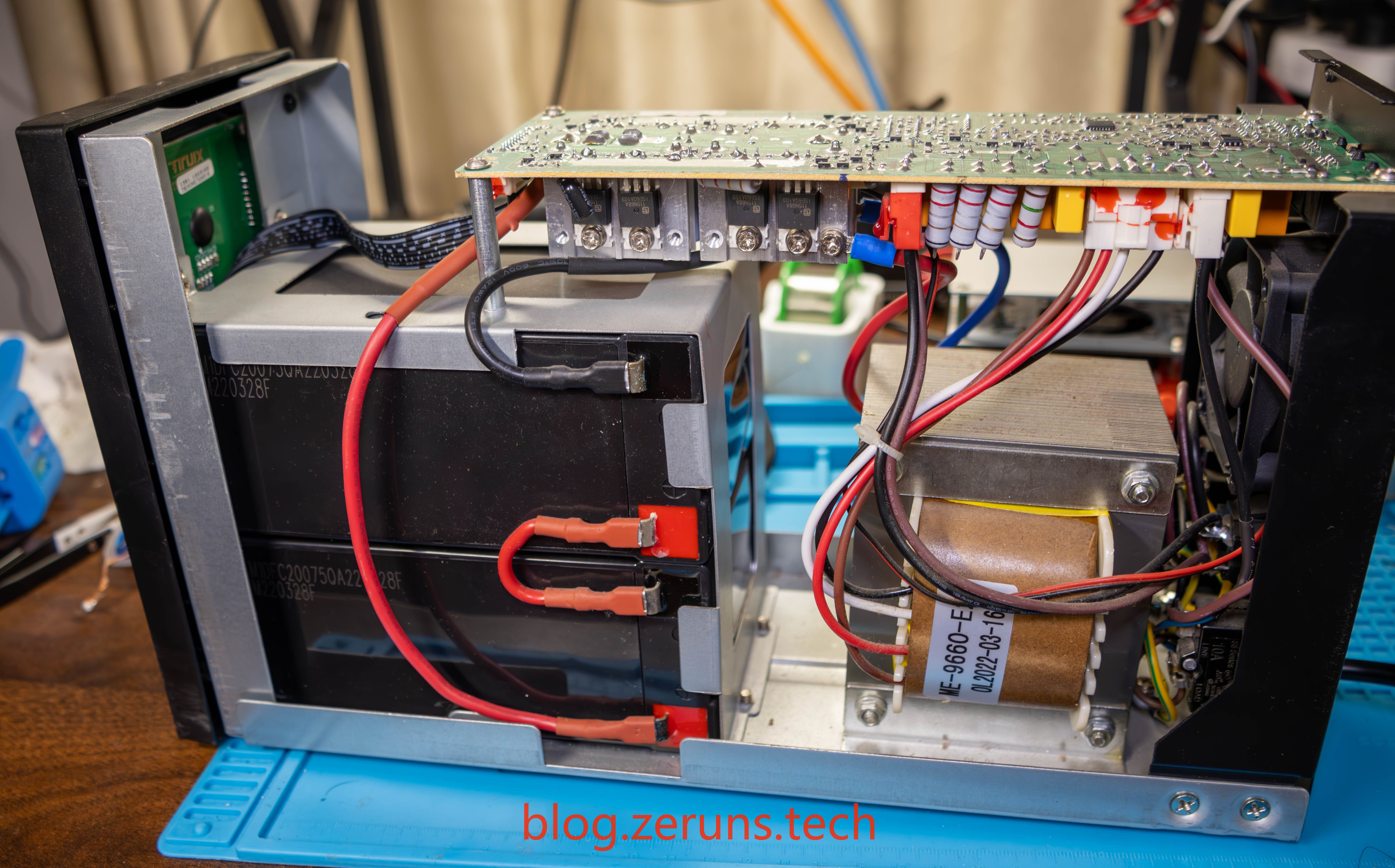
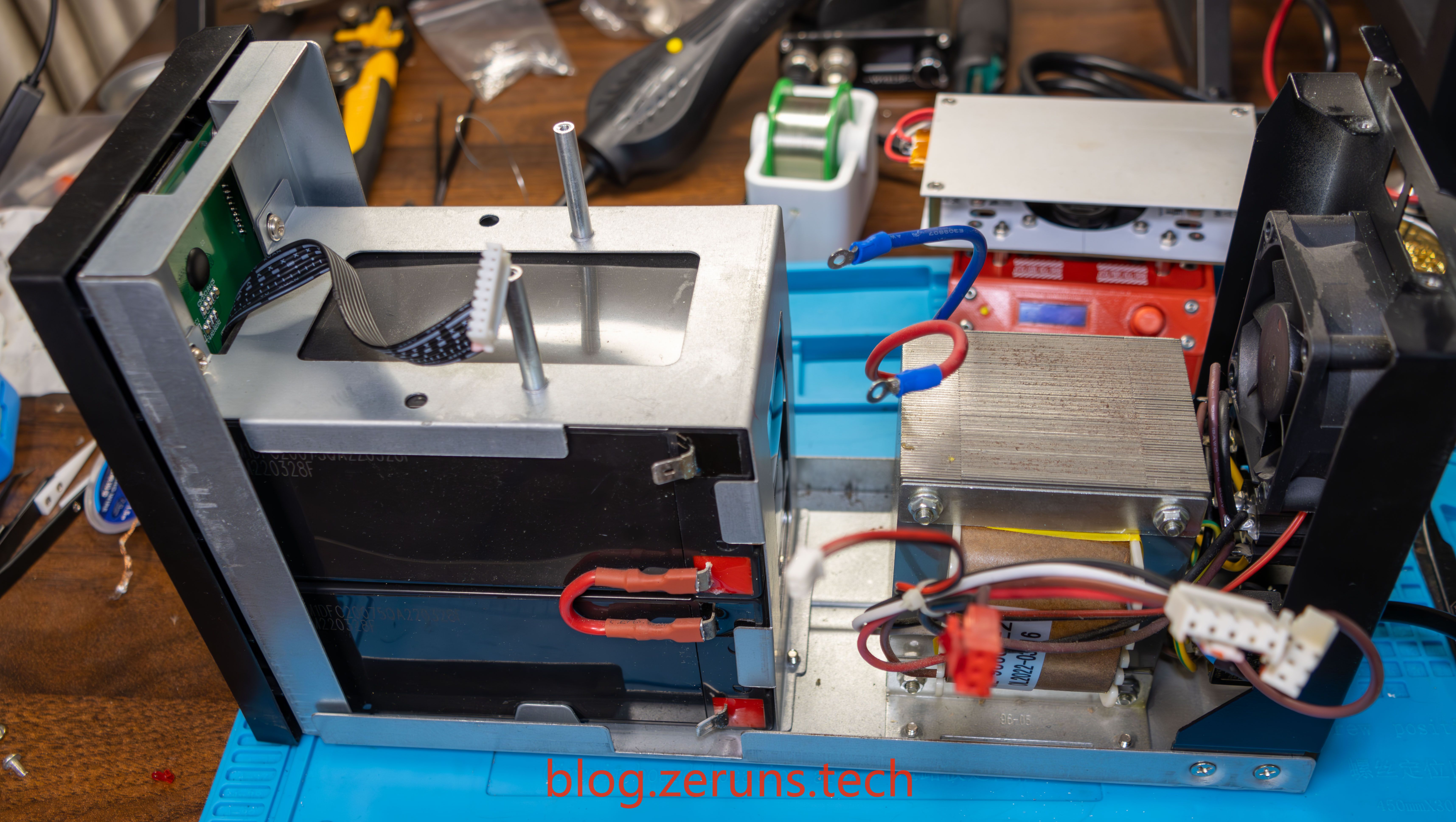
Side
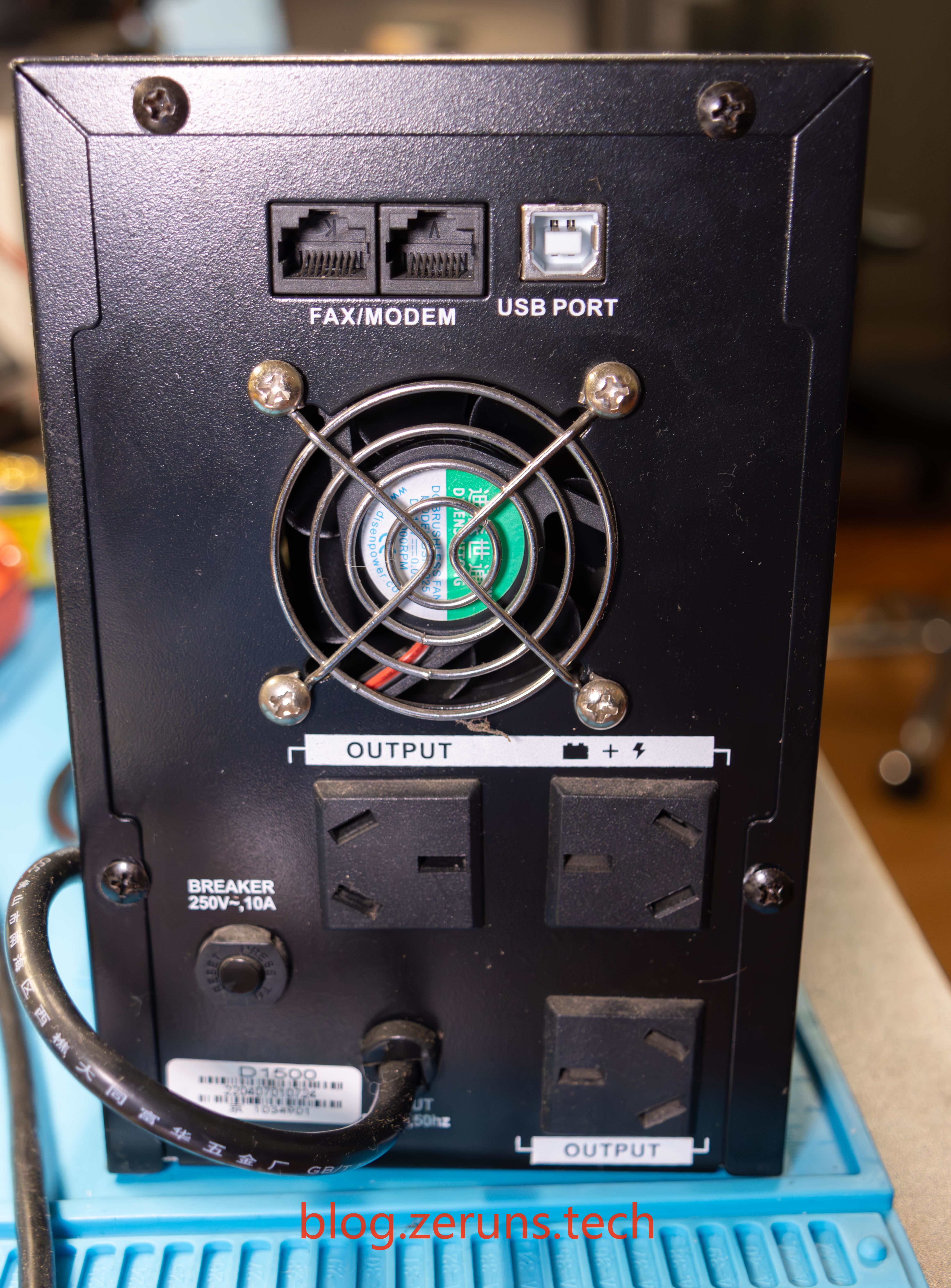
Back
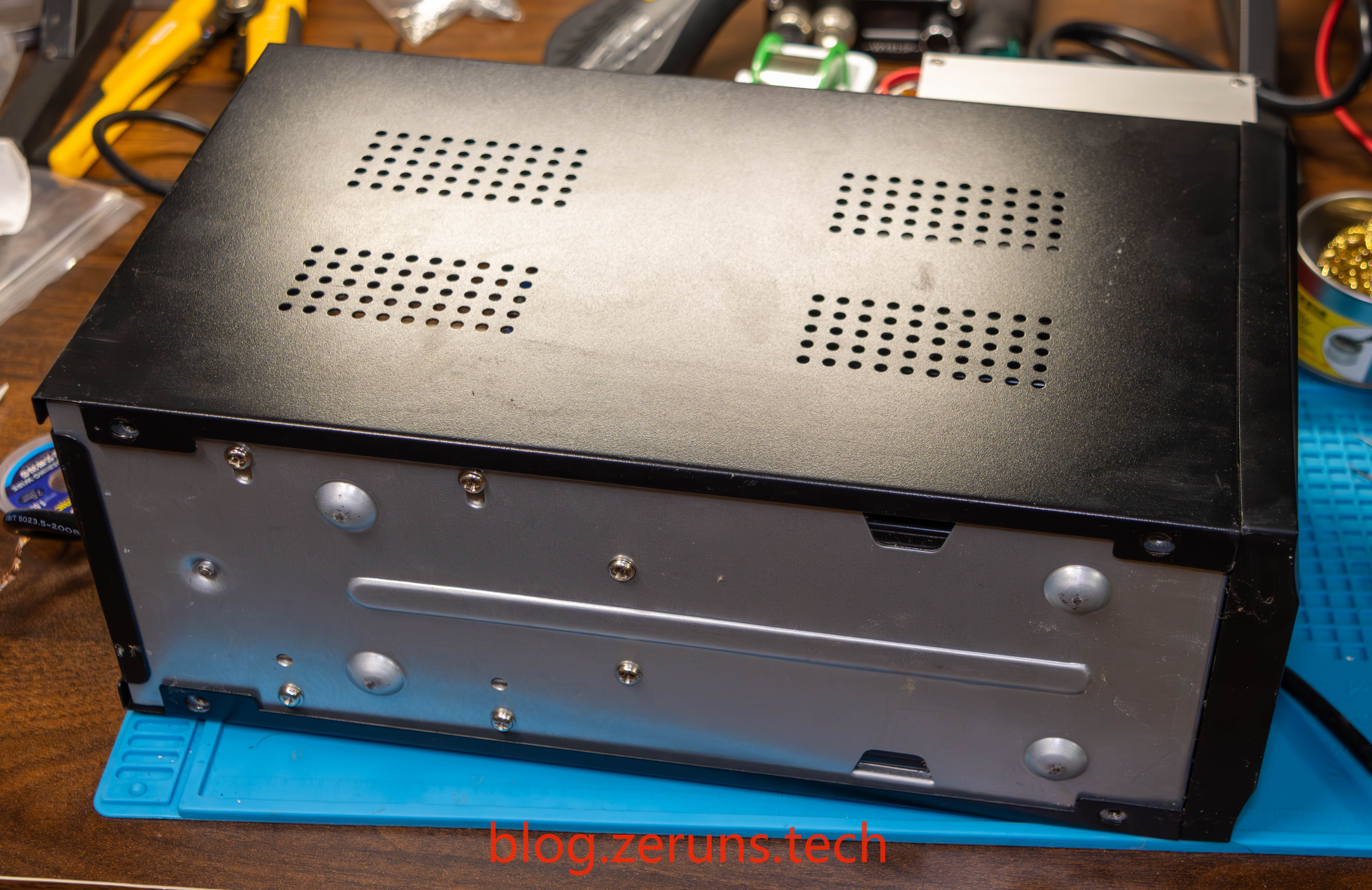
Bottom
After removing the cover, the side view reveals a transformer and two 12V 9AH lead-acid batteries connected in series, with the circuit board mounted on top.
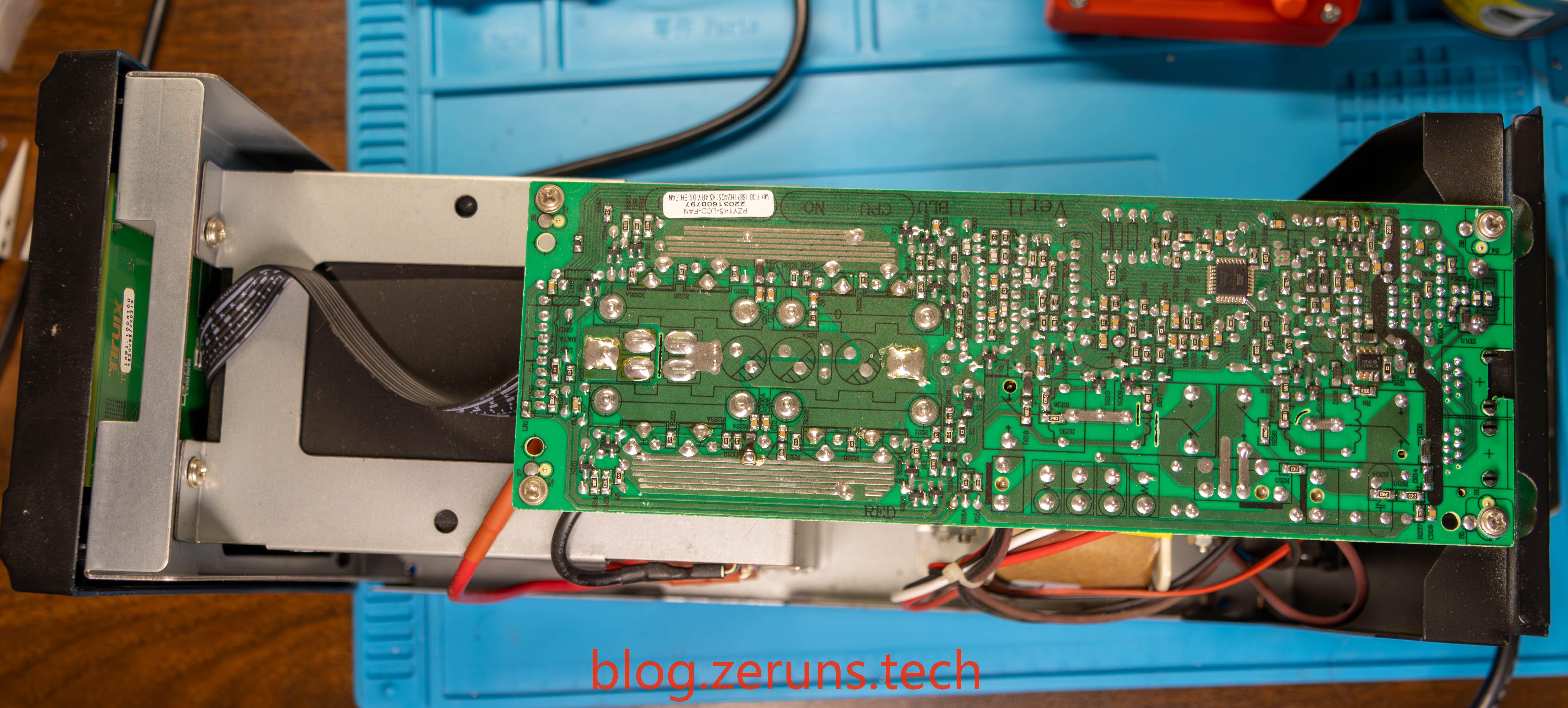
Top After Disassembly
The main control chip is the ATmega168PA, an 8-bit microcontroller.
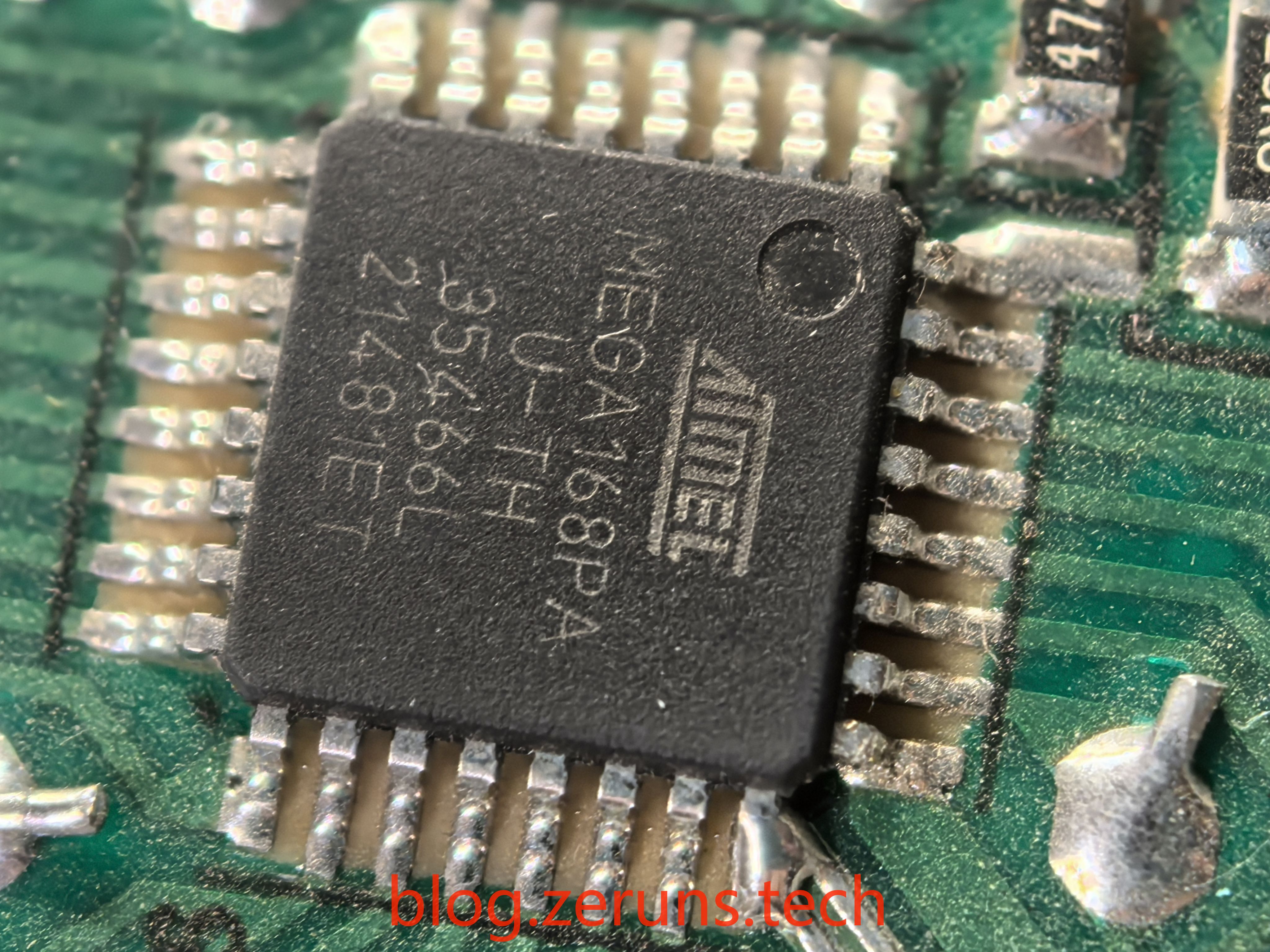
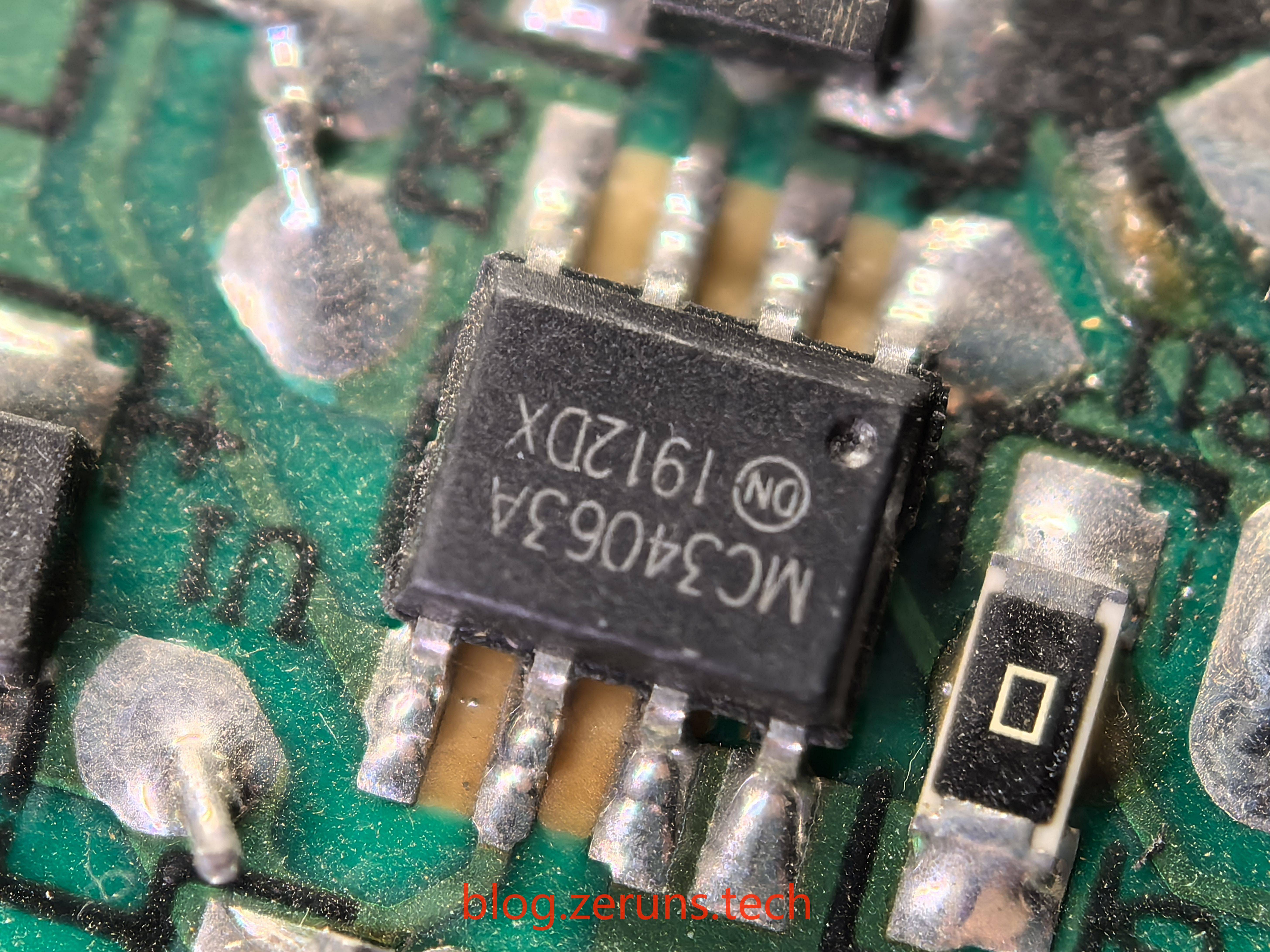
Next to it is a DC-DC buck converter chip, the MC34063A, which is likely used to supply power to the microcontroller and the relay.
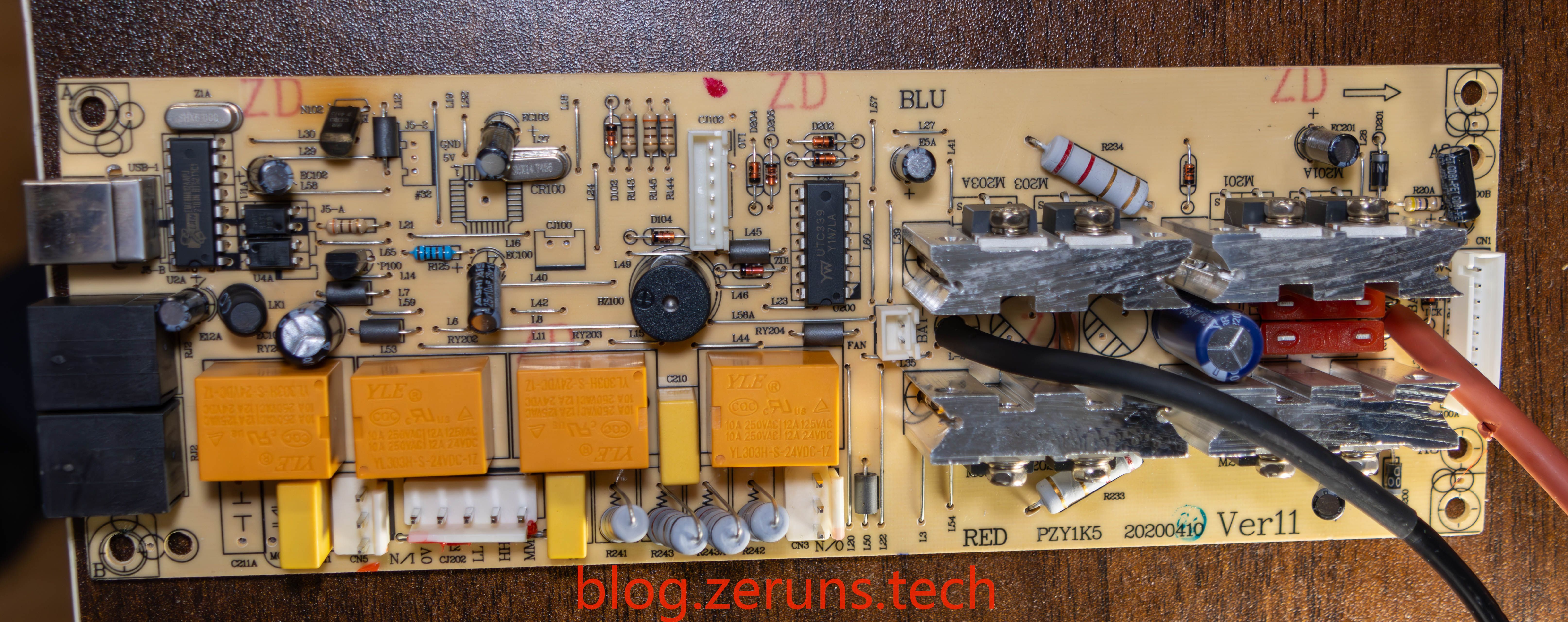
Front of the Circuit Board

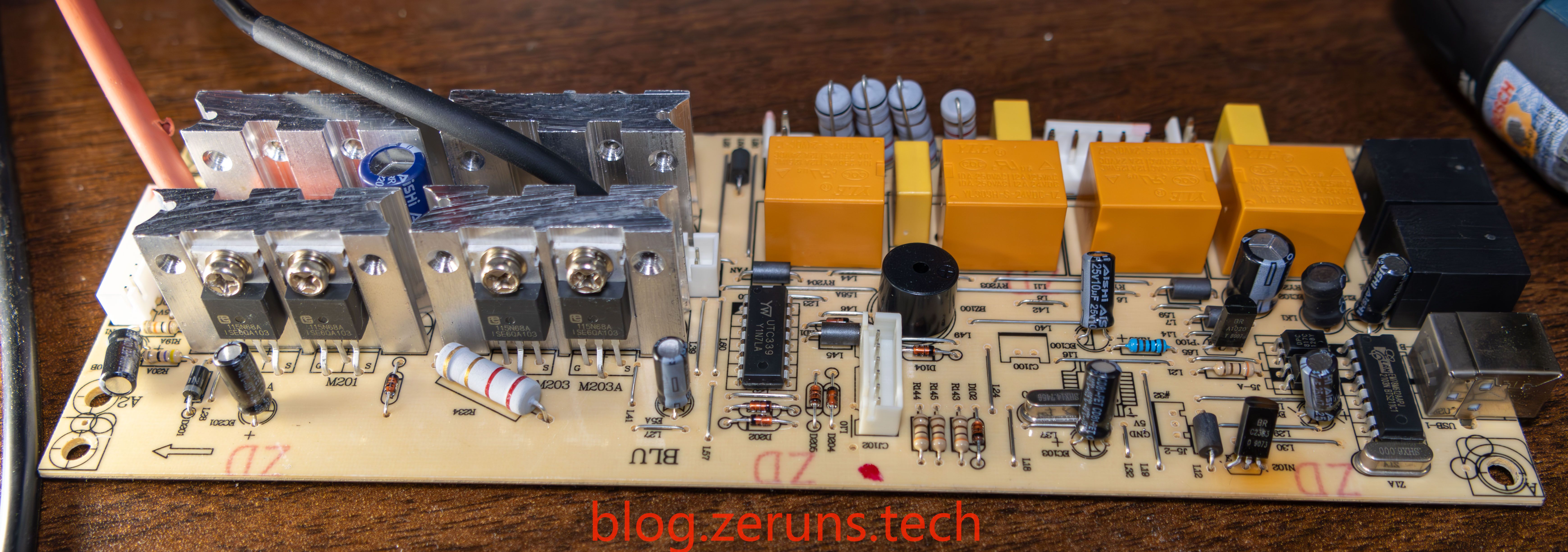
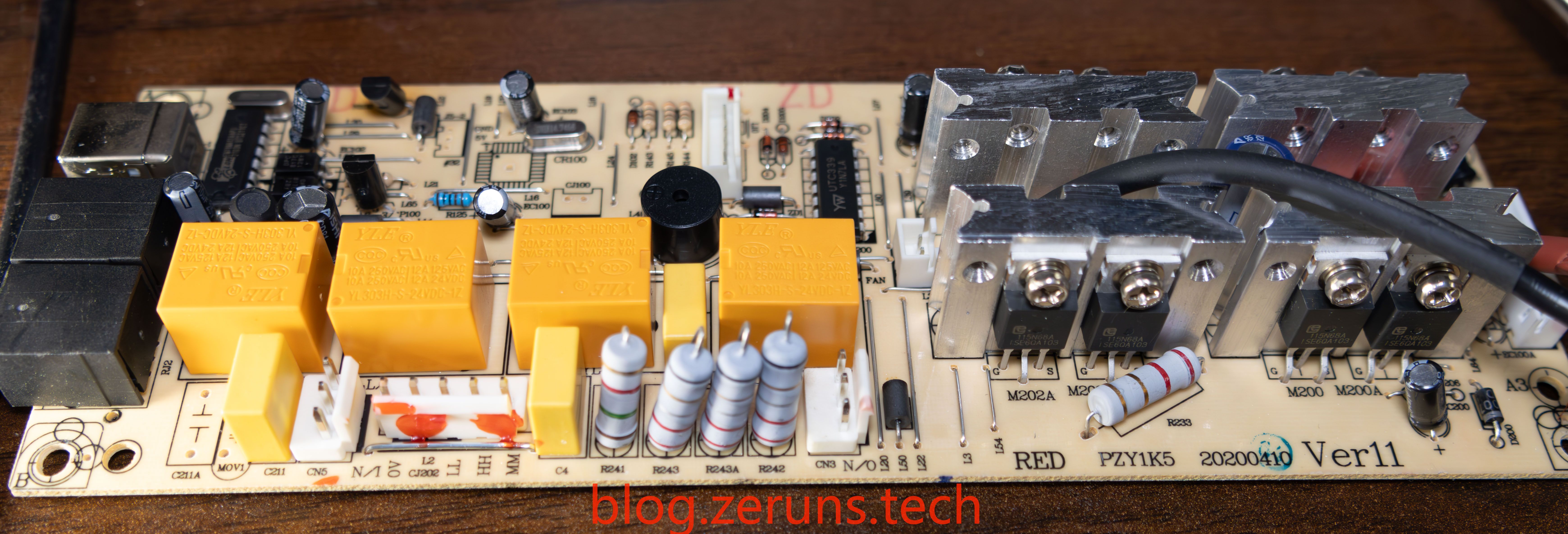
The UTC339 chip, a four-channel voltage comparator, can be seen here.

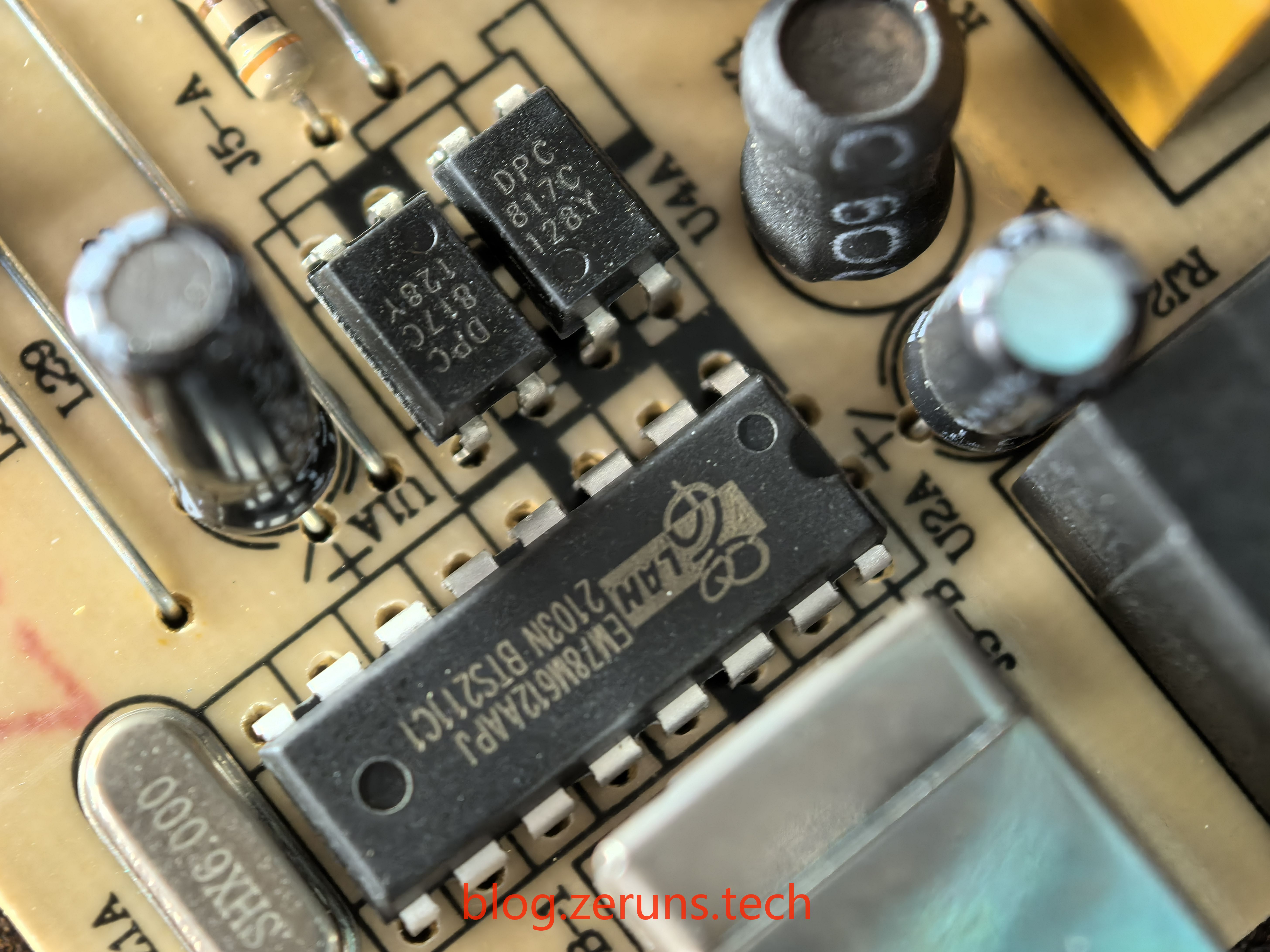
The EM78M612AAPJ is a microcontroller produced by Elan Microelectronics Corporation, part of the EM78M612 series. This series is based on an 8-bit RISC architecture with a Universal Serial Bus (USB) interface, making it well-suited for low-speed USB applications. It is widely used in devices or systems that require serial communication, especially in USB applications, as it can automatically recognize and decode standard USB commands—simplifying firmware design.
All the capacitors on the board are from the AISHI (艾华) brand.
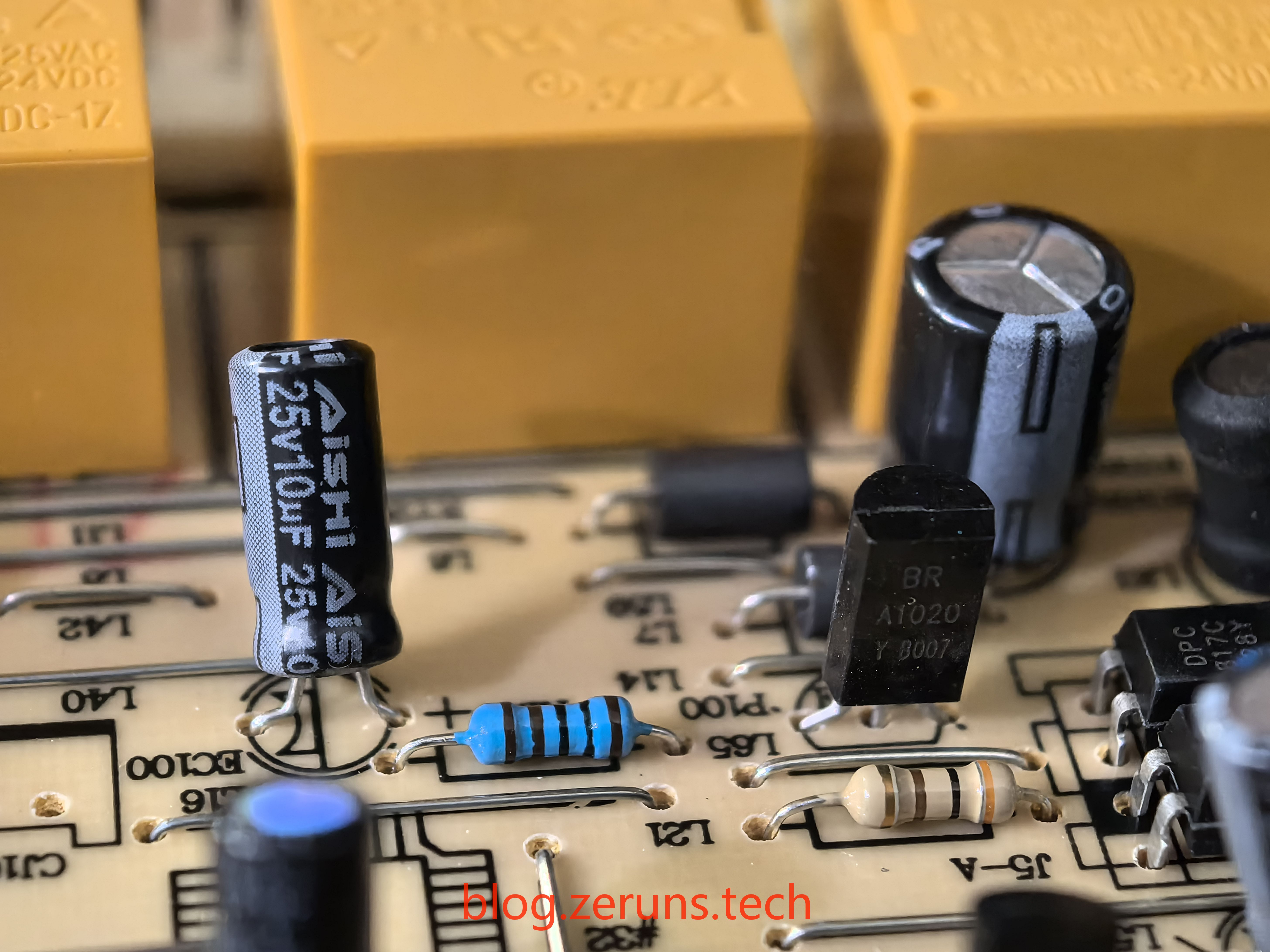
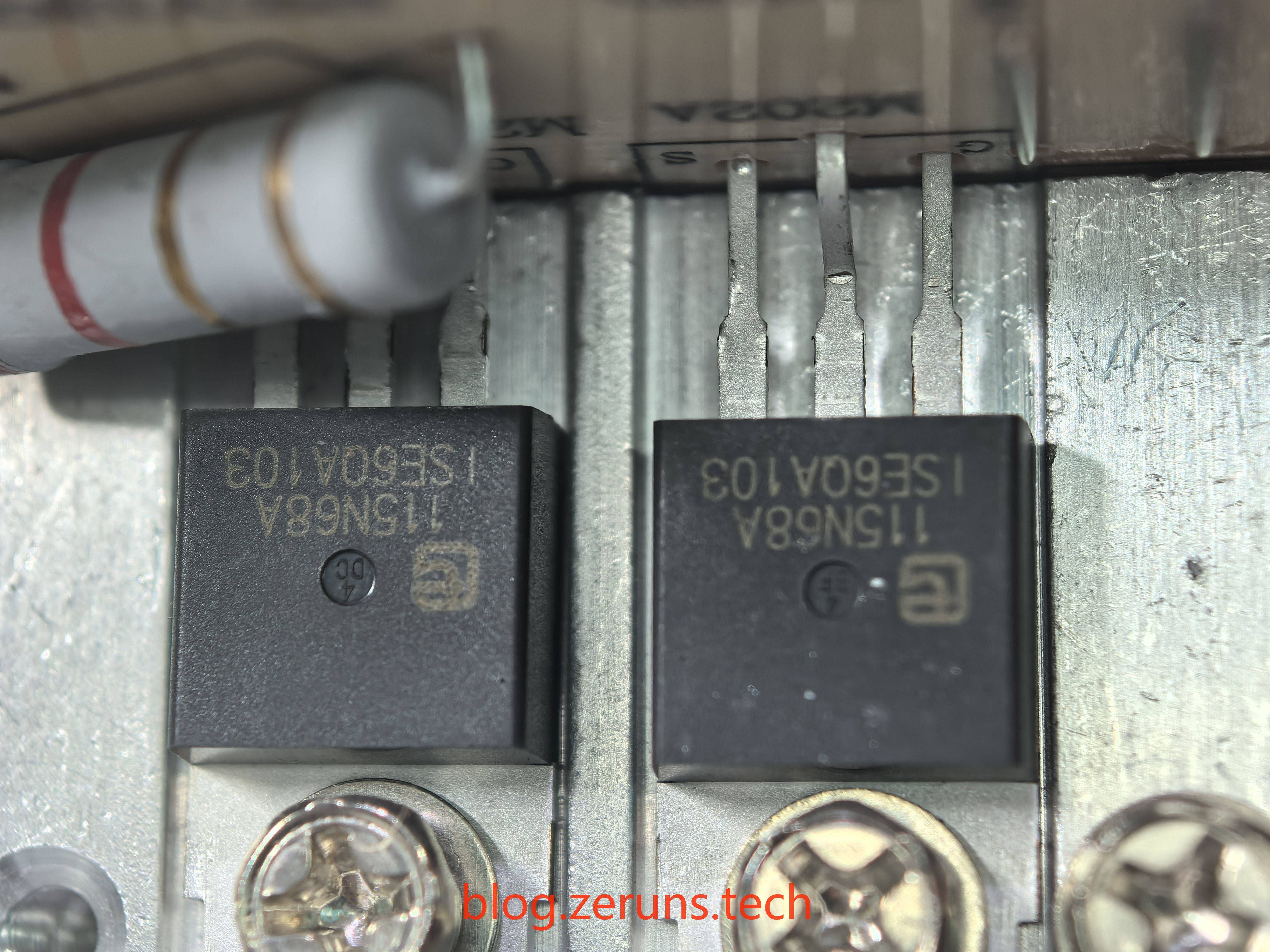
The MOSFET is the 115N68A from Wuxi Unigroup, rated at 68V and 115A.
After removing the inverter circuit board:
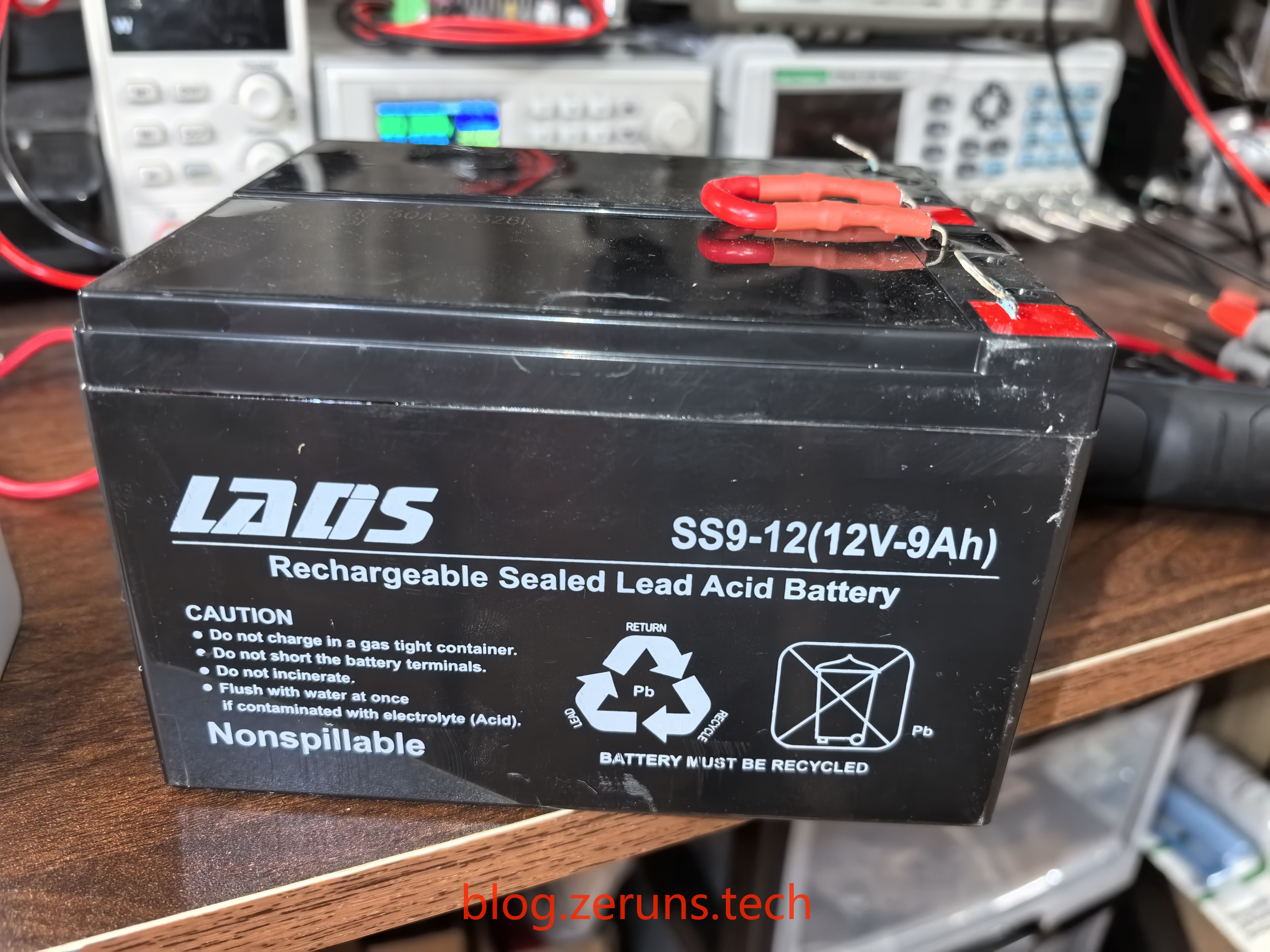
The battery is from the LADS brand, model SS9-12—a 12V 9AH lead-acid battery—with two connected in series.
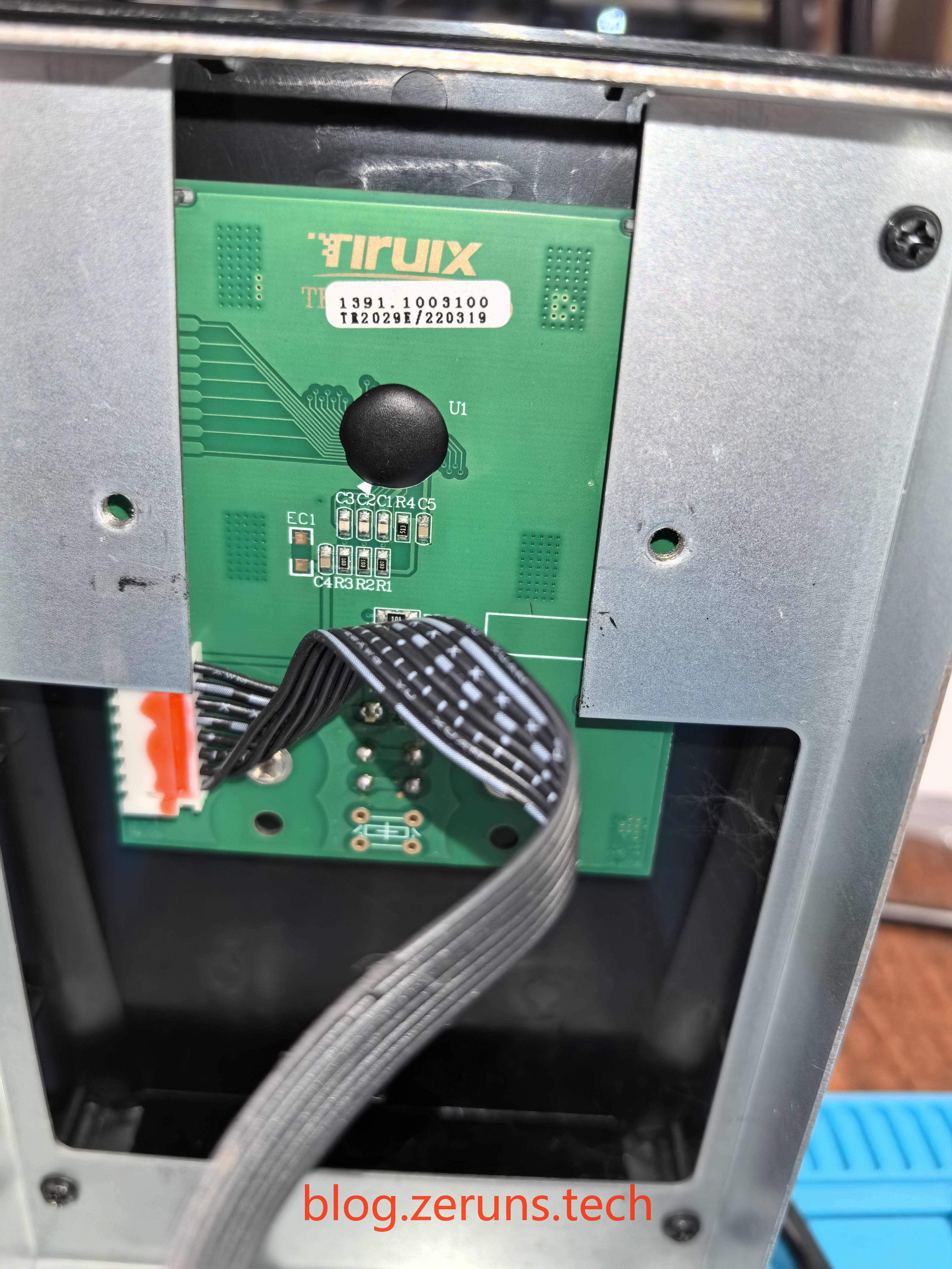
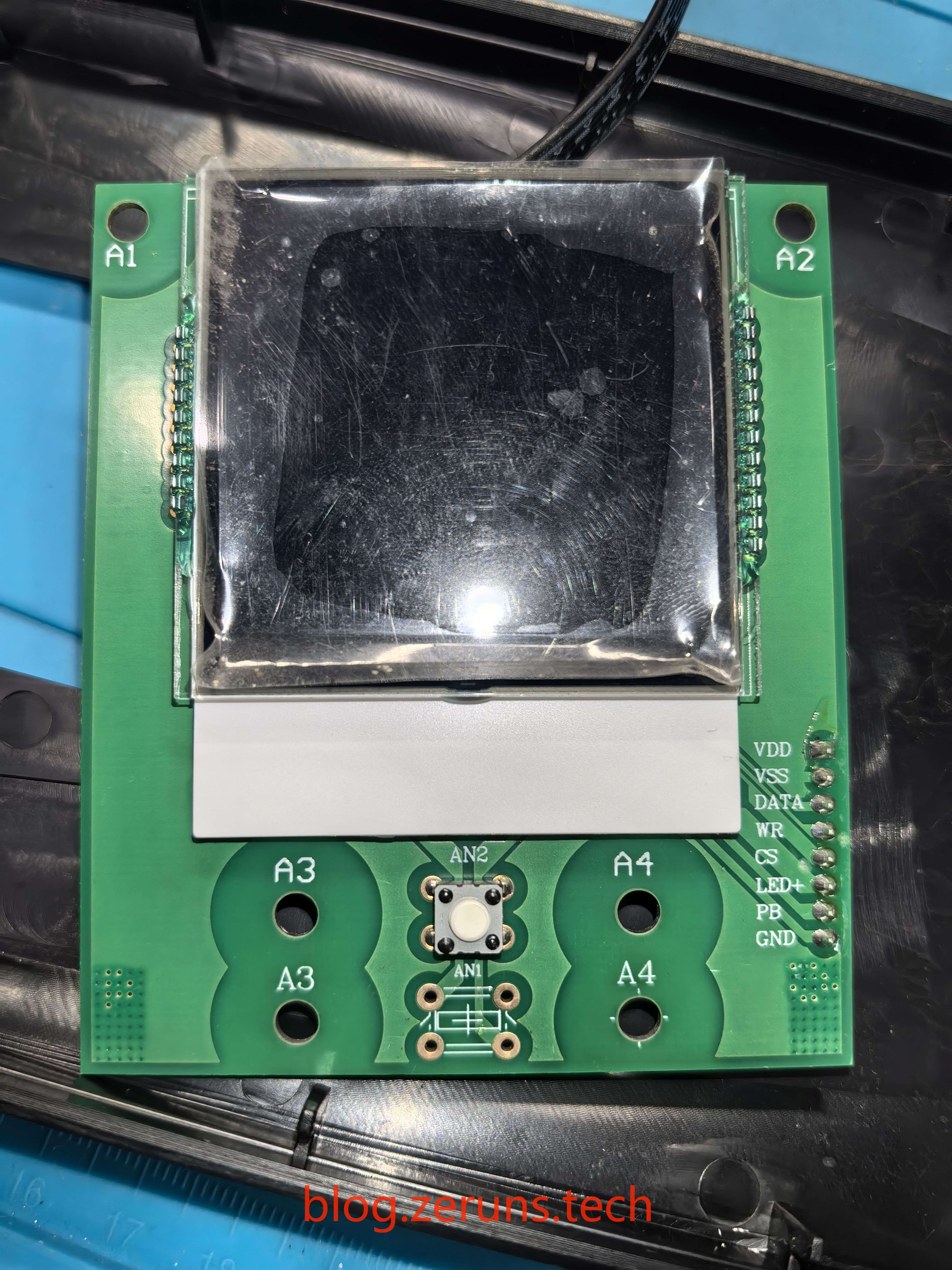
Front LCD Display Circuit Board

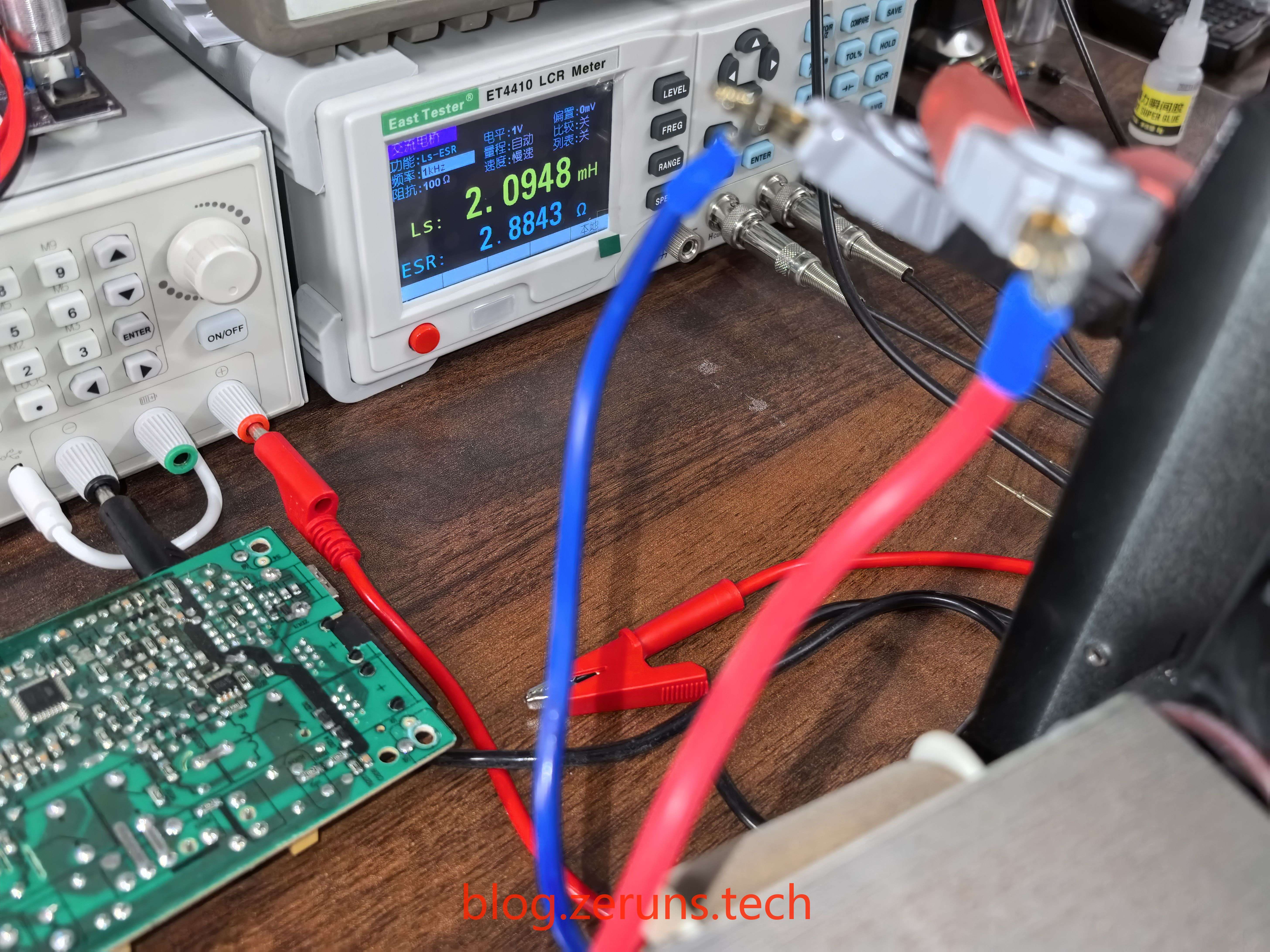
Using an LCR meter, the inductance of the transformer’s primary coil was measured to be 2.0948mH.
Analysis
Electronics/Microcontroller Technical Exchange QQ Group: 2169025065
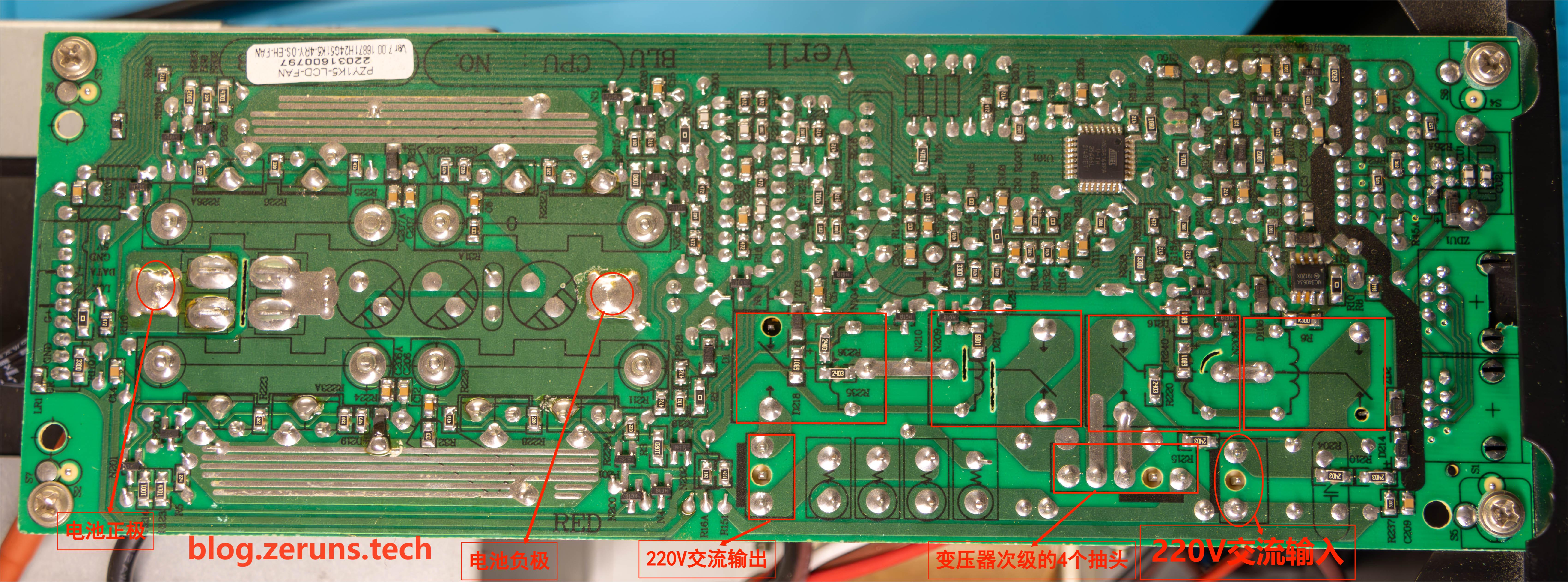
After a brief inspection of the wiring, I sketched a rough diagram of the UPS's inverter section. This is only a simplified schematic—the various details and control circuits are not included.
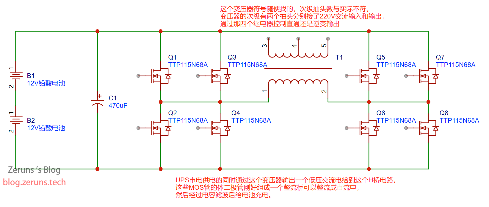
This UPS inverter appears to be a line-frequency inverter. It uses MOSFETs arranged in an H-bridge configuration, which are controlled by PWM signals to generate a 50Hz low-voltage square wave. This square wave is then fed into a line-frequency transformer to step up the voltage to 220V AC.
(For context, the basic principle of a high-frequency inverter is to first use a DC-DC converter to boost the voltage to around 400V. Then, using an SPWM signal, the MOSFETs generate a high-frequency AC signal. This signal is filtered through an LC filter (an inductor and capacitor) to extract a low-frequency AC output. High-frequency inverters generally have much higher conversion efficiency than line-frequency inverters. My description may not be entirely precise—consider it a rough overview. Experts are welcome to elaborate in the comments.)
The secondary side of this line-frequency inverter features four taps, which are controlled by four relays to achieve functions such as direct mains output, mains-based battery charging, and battery inverter output. You can refer to the PCB image below where I have labeled the various interfaces.
While the UPS is powered by the mains, it also outputs a low-voltage AC via the line-frequency transformer to the H-bridge circuit (effectively, the transformer's primary and secondary windings are swapped at this point). The body diodes of the MOSFETs in the H-bridge form a rectifier bridge that converts the AC to DC. After capacitor filtering, this DC is used to charge the battery.
This circuit essentially functions as a bidirectional AC-DC converter.
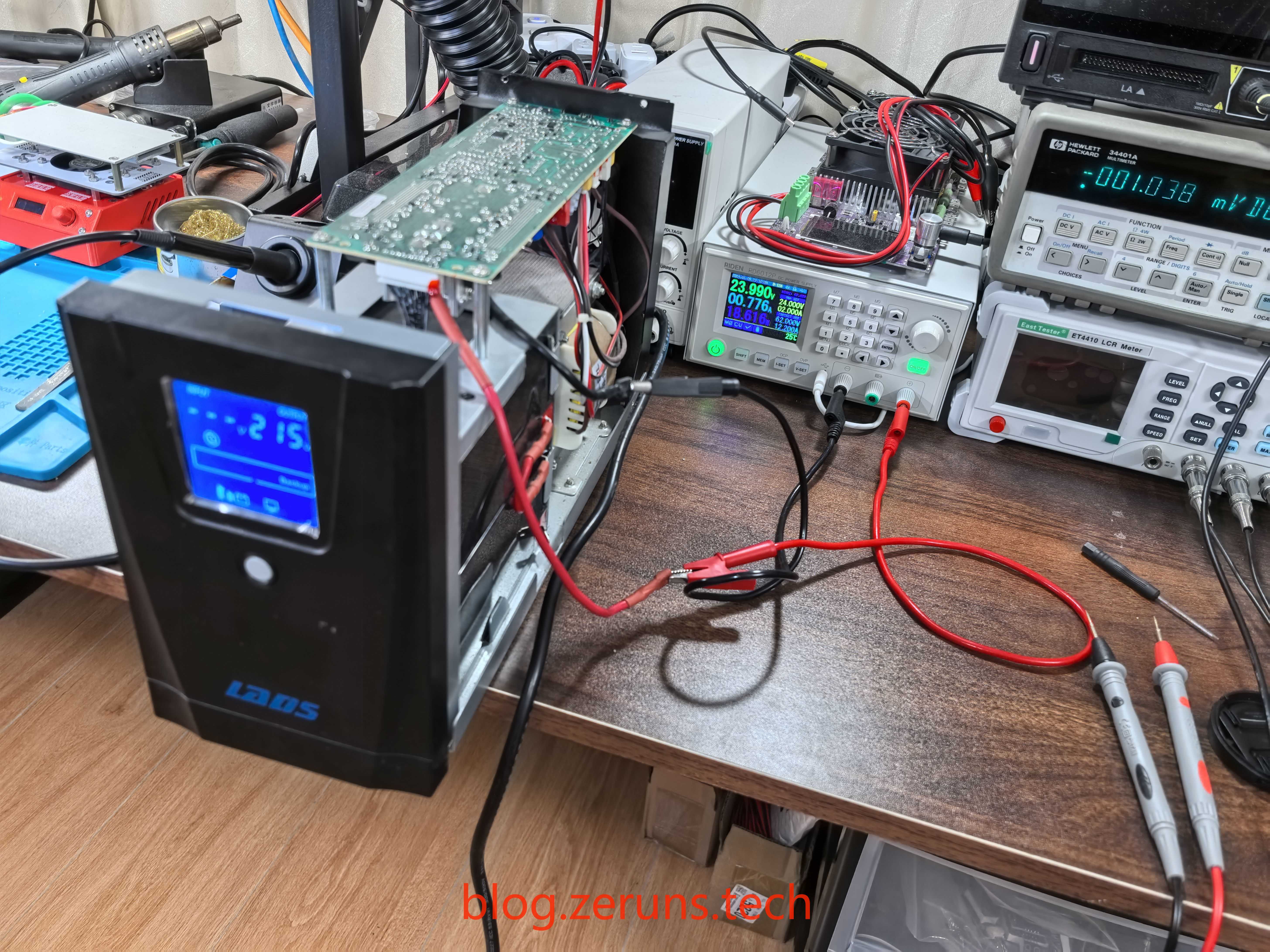
The two wires connected to the battery were hooked up to an adjustable power supply. With the power supply set to output 24V and the UPS turned on, the no-load power consumption was around 18 watts—which is somewhat high for no-load conditions.
I tested the inverter's conversion efficiency: with an input power of 104W and an output power of 80W, the efficiency comes out to be roughly 77%.
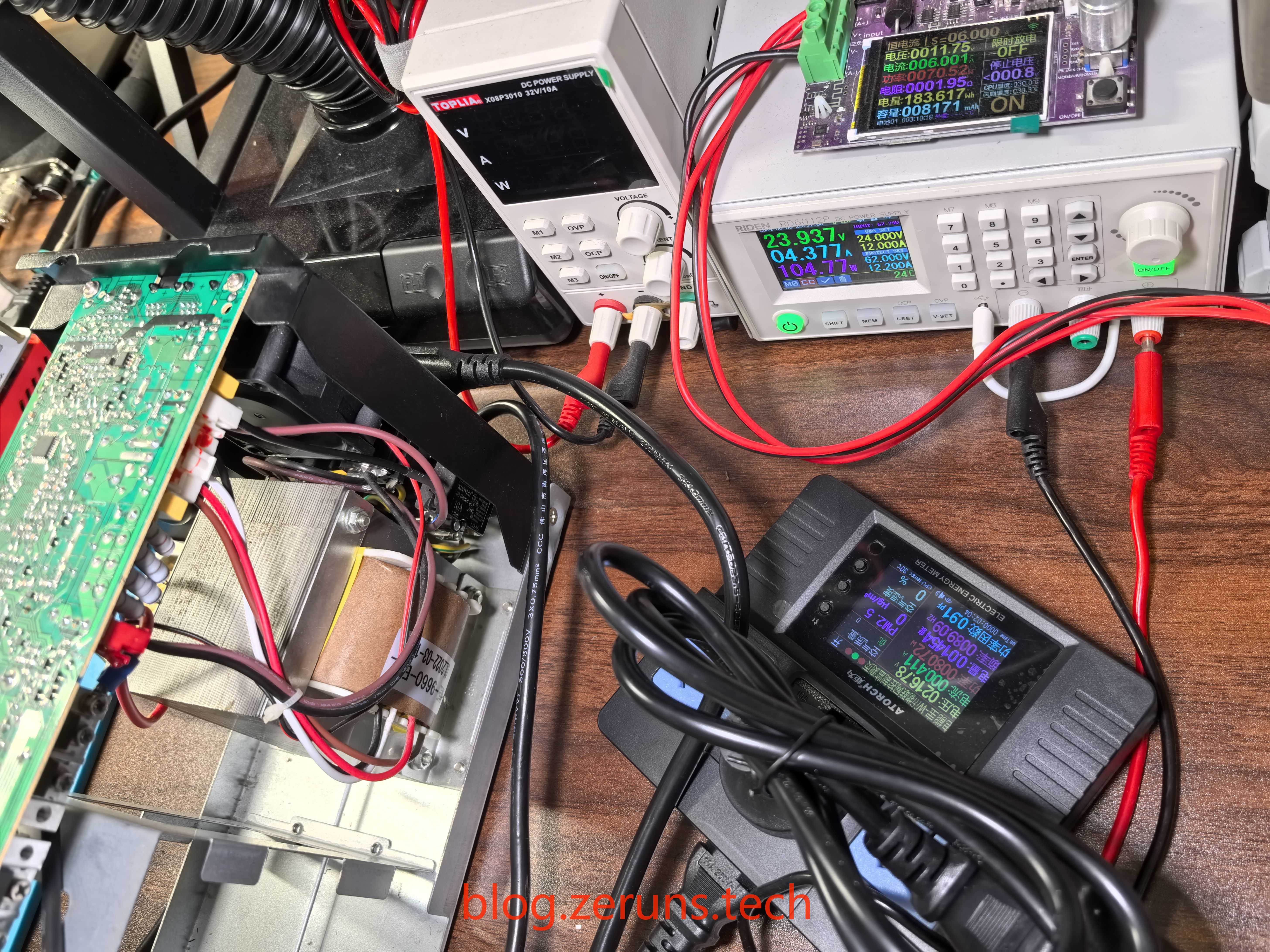
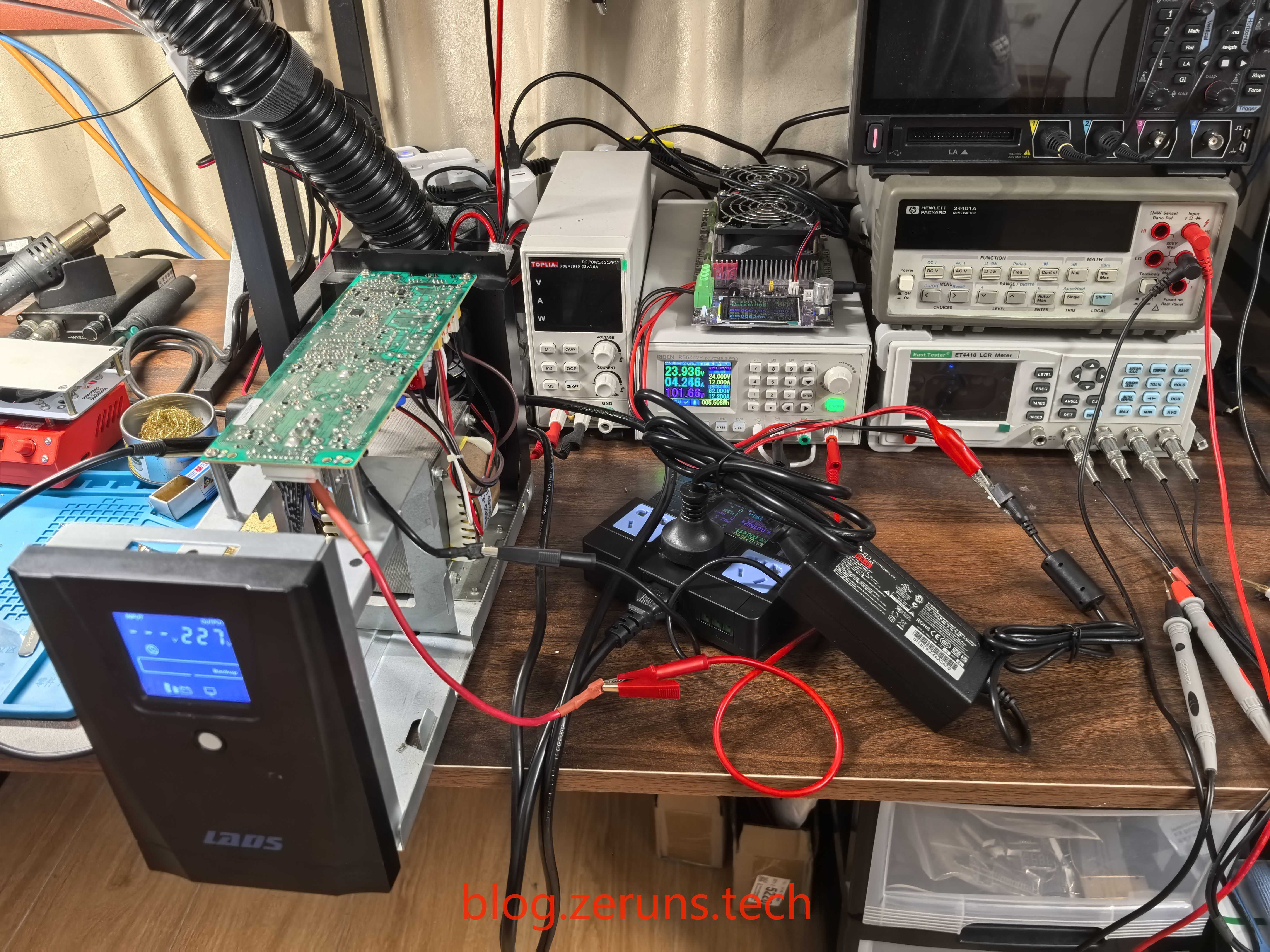
I also tried charging the battery directly. Within a few seconds, the voltage (across the two batteries in series) reached 24V, but the charging current was very small. After disconnecting the charger, the battery voltage dropped rapidly.
Recommended Reading
- High Cost-Effective and Affordable VPS/Cloud Server Recommendations: https://blog.zeruns.com/archives/383.html
- Minecraft Server Setup Tutorial: https://blog.zeruns.com/tag/mc/
- No-Code Blog Website Setup! An Ultra-Detailed Personal Blog Setup Tutorial: https://blog.zeruns.com/archives/783.html
- Yuyun Ningbo 8272CL – Performance Evaluation of a High Bandwidth, High-Defense Cloud Server with Up to 500Mbps Bandwidth and 1TB Cloud Storage: https://blog.zeruns.com/archives/789.html
- Open Source: STM32-Based Synchronous Rectification Buck-Boost Digital Power Supply: https://blog.zeruns.com/archives/791.html


Comment Section