


OWON (Lilliput) HDS160 4½‑digit Handheld Oscilloscope Multimeter – Quick Unboxing, Review, and Teardown.
Preface
Recently I bought a 4½‑digit multimeter, the OWON HDS160. The main reason I chose it is its oscilloscope function, which works directly with standard multimeter test leads—no need to swap to oscilloscope probes. You can directly measure voltage or current waveforms using the same probes. Although the bandwidth is only 1 MHz, it's more than enough for my needs; for higher‑frequency signals I'll just use a dedicated oscilloscope. What really makes it attractive is how convenient it is for measuring current waveforms, plus it can automatically detect which input jack the probes are plugged into and switch between voltage/current ranges accordingly. Very handy.
I bought it for 365 RMB.
▶ HDS160 / HDS120 Purchase Links:
- Taobao (third‑party store): https://s.click.taobao.com/7ZVqsen
- Taobao OWON Official Store: https://s.click.taobao.com/ovsosen
- JD.com: https://u.jd.com/lDdfYPj
▶ Electronics / MCU Technical Discussion QQ Group: 2169025065
▶ eeClub – Electronics Engineer Community: https://bbs.eeclub.top/
Specifications
1. Multimeter Specifications
| Measurement Type | Measurement Range | Max Accuracy |
|---|---|---|
| DC Voltage (V) | 60.000 mV / 600.00 mV / 6.0000 V / 60.000 V / 600.00 V / 1000.0 V | ±(0.05% + 5 digits) |
| AC Voltage (V) | 600.00 mV / 6.0000 V / 60.000 V / 600.00 V / 750.00 V | ±(0.1% + 30 digits) |
| DC Current (A) | 600.00 μA / 6000.0 μA / 60.000 mA / 600.00 mA / 6.0000 A / 10.000 A | ±(0.15% + 10 digits) |
| AC Current (A) | 600.00 μA / 6000.0 μA / 60.000 mA / 600.00 mA / 6.0000 A / 10.000 A | ±(0.5% + 20 digits) |
| Resistance (Ω) | 600.00 Ω / 6.0000 kΩ / 60.000 kΩ / 600.00 kΩ / 6.0000 MΩ / 60.000 MΩ | ±(0.15% + 10 digits) |
| Capacitance (F) | 6.000 nF / 60.00 nF / 600.0 nF / 6.000 μF / 60.00 μF / 600.0 μF / 6.000 mF / 60.00 mF | ±(2.0% + 20 digits) |
| Frequency (Hz) | 60.00 Hz / 600.00 Hz / 6.0000 kHz / 60.000 kHz / 600.00 kHz / 6.0000 MHz / 60.000 MHz | ±(0.2% + 10 digits) |
| Duty Cycle | 0.1%–99.9% (typical: Vrms = 1 V, f = 1 kHz) | ±(1.2% + 3 digits) |
| Duty Cycle | 0.1%–99.9% (≥ 1 kHz) | ±(2.5% + 3 digits) |
| Diode Test | 3.0000 V | ±(1.0% + 10 digits) |
| Continuity | 1000.0 Ω | – |
| Max Display | 60000 counts | – |
2. Oscilloscope Specifications
| Parameter | Specification | Parameter | Specification |
|---|---|---|---|
| Analog Bandwidth | 1 MHz (ACV range only) | Max Sampling Rate | 5.0 MSa/s |
| Channels | 1 | Input Impedance | ≈ 10 MΩ |
| Time Base Range | 2.5 μs–10 s/div | Time Base Accuracy | ±(0.01% + 0.1 div) |
| Voltage Vertical Sensitivity | 30 mV–500 V/div | Current Vertical Sensitivity | 100 μA–5 A/div |
| Vertical Amplitude Accuracy | ±(5% + 0.2 div) | Measurements | Vmax, Vmin, Vp‑p, Vavg, Vrms, Hz |
| Max Voltage Input | 1000 V DC + AC peak | Max Current Input | 15 A DC + AC peak |
| Trigger Mode | Auto / Normal / Single | Trigger Edge | Rising / Falling |
| Auto Setup | Time base / Vertical scale / Trigger level | – | – |
3. Other Features
| Feature | Specification | Feature | Specification |
|---|---|---|---|
| Low Battery Indicator | √ | Auto Power‑off | √ |
| Relative Measurement | √ | Backlight | √ |
| Input Protection | √ | Input Impedance | ≥ 10 MΩ |
| Safety Rating | CAT III 1000 V | Display | 2.8‑inch IPS LCD |
| Weight (without battery) | 0.35 kg | Battery | Single 18650 Li‑ion 3.7 V |
| Dimensions (L × W × H) | 188 mm × 93 mm × 41.5 mm | – | – |
Unboxing
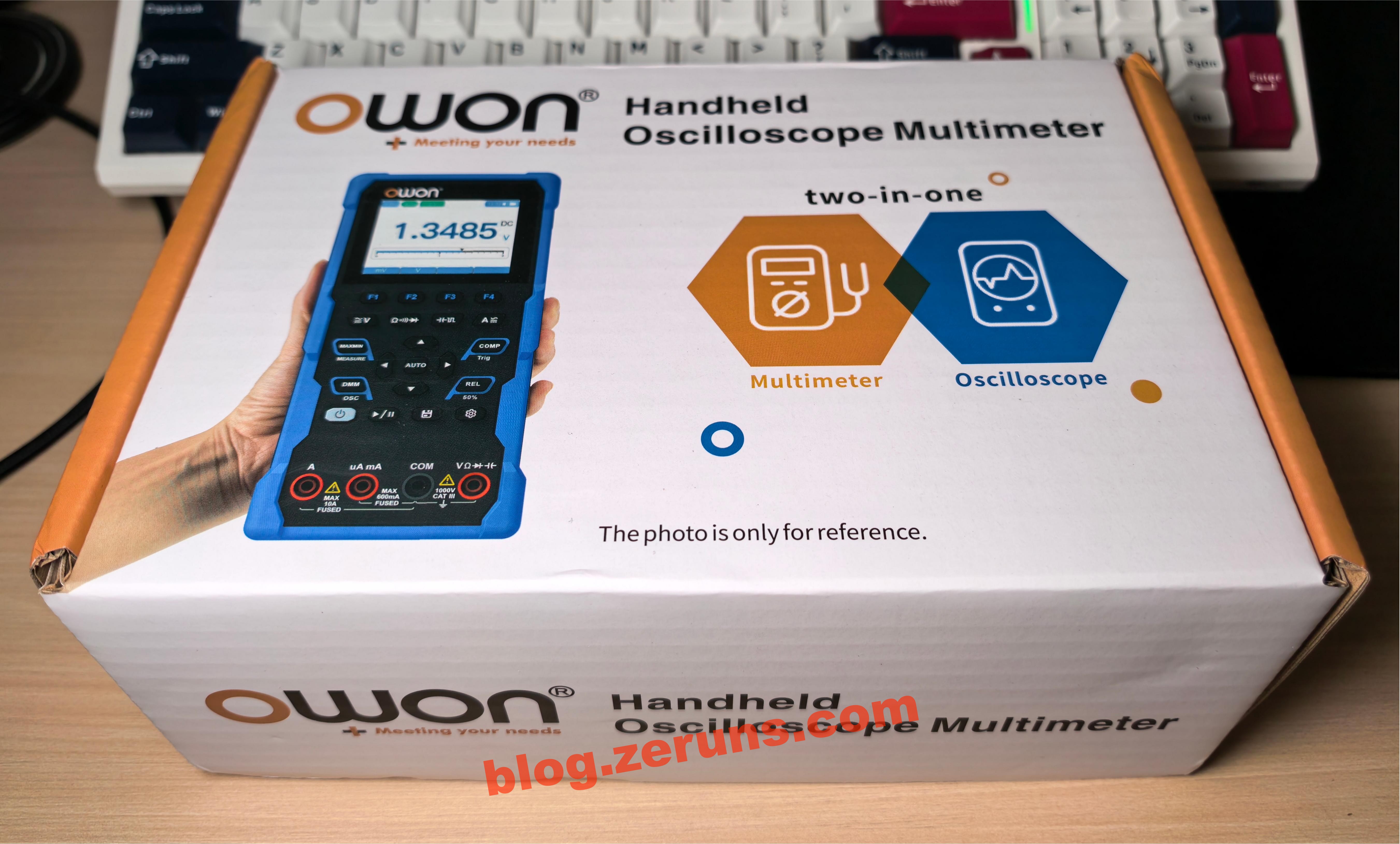
The front of the outer box is printed with “OWON Handheld Oscilloscope Multimeter”.
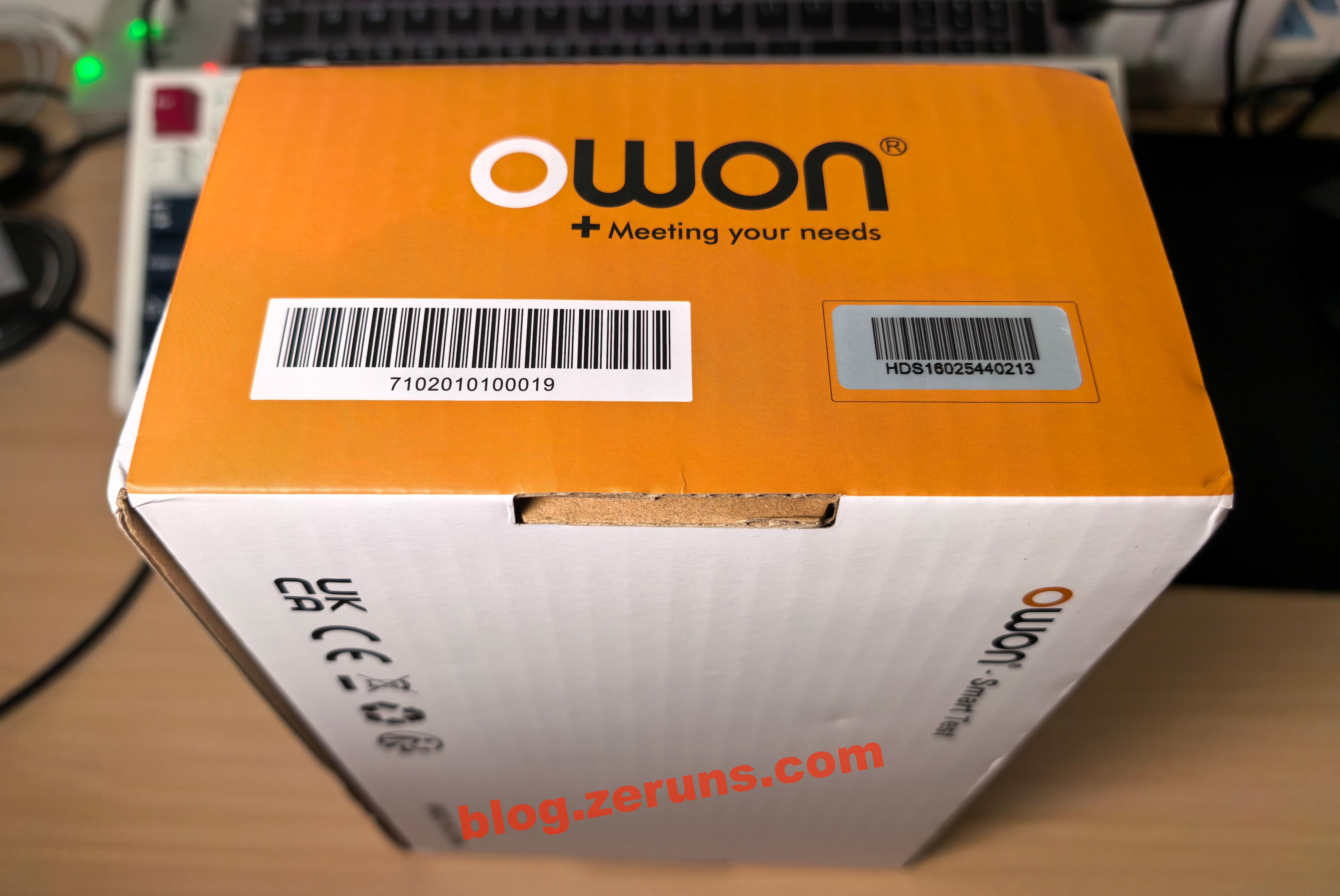
On the side of the box, there's a product barcode and a serial number label.
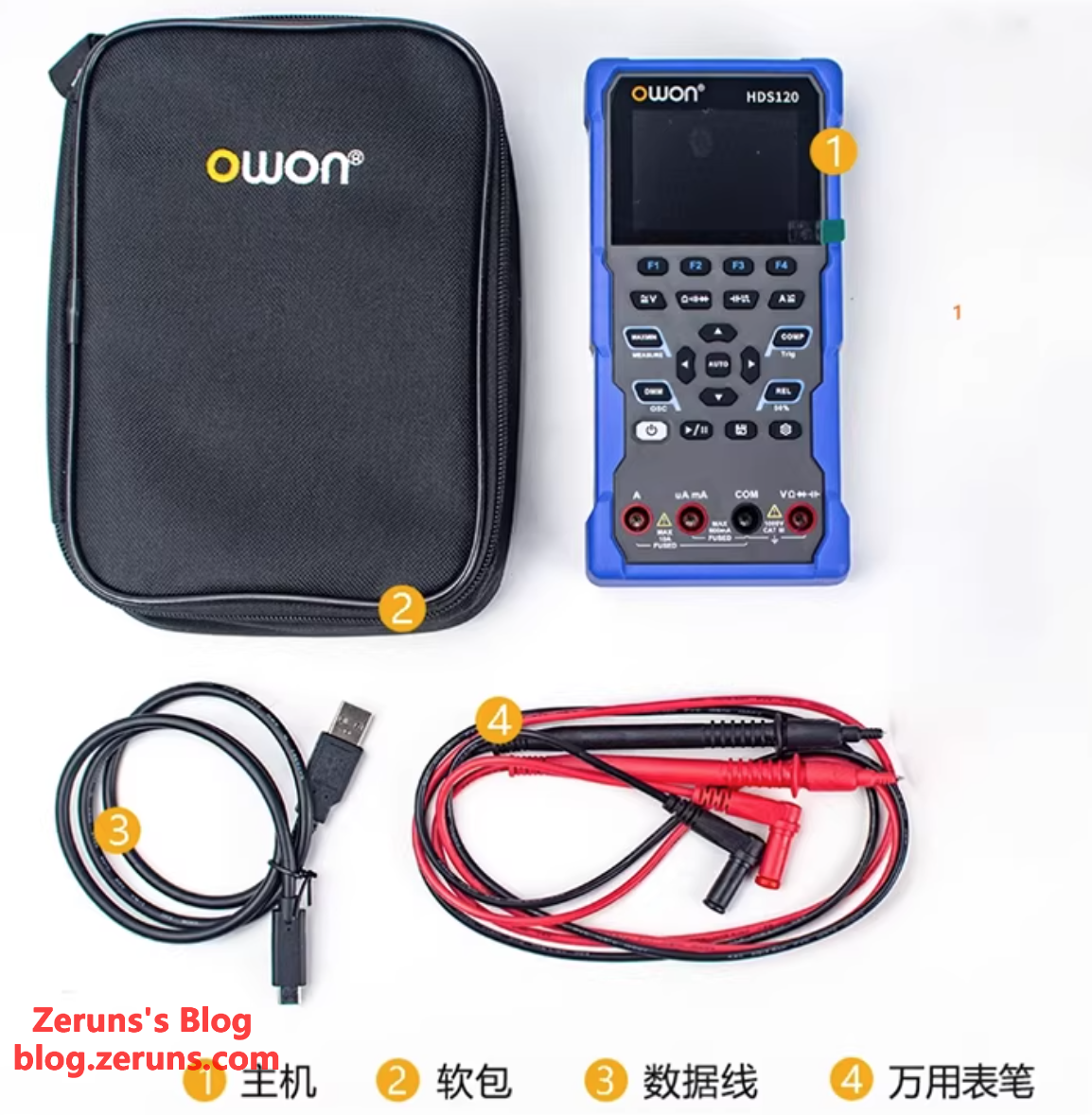
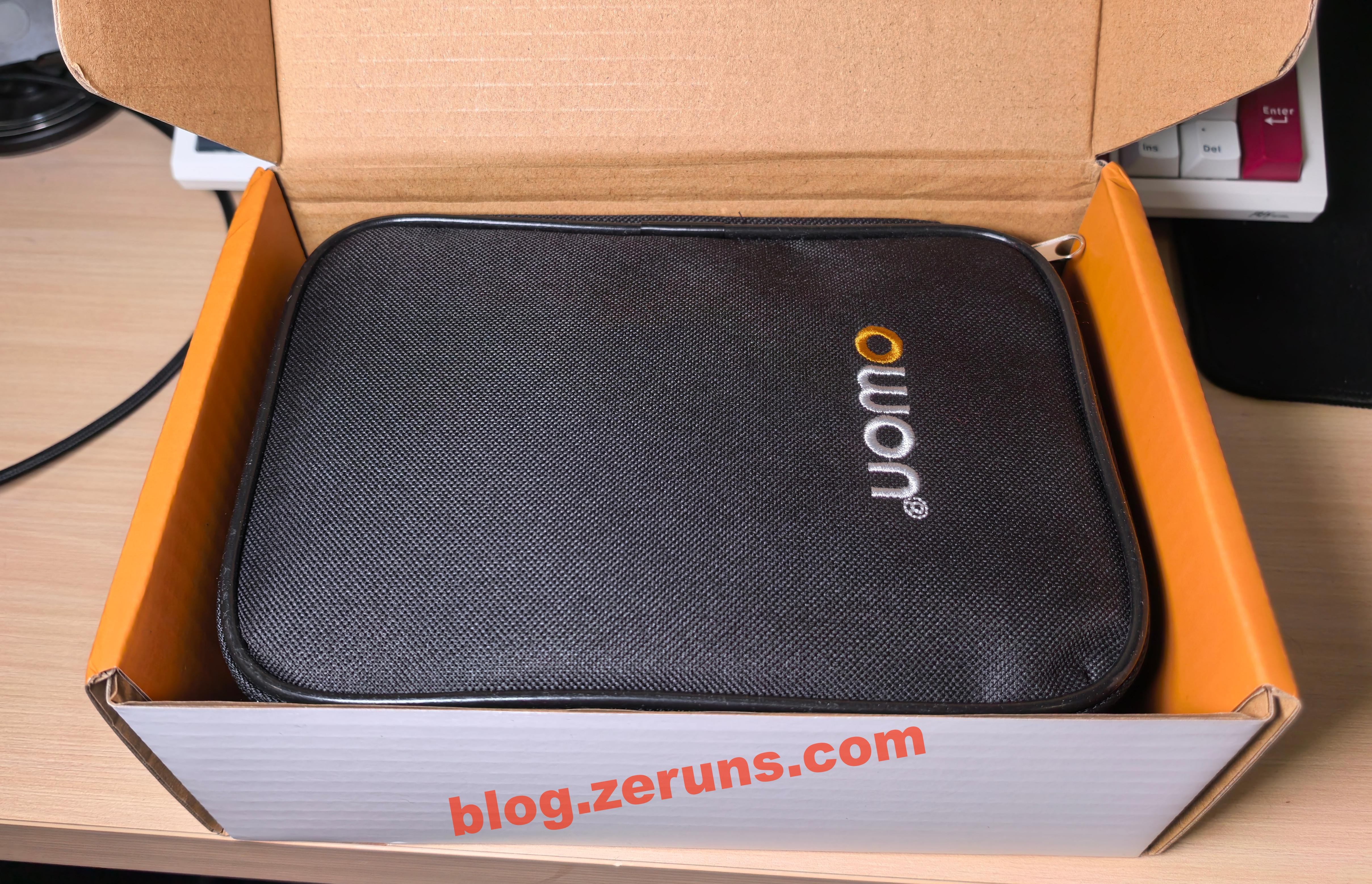
After opening the box, the first thing you see is a carrying case. Everything is packed inside it.
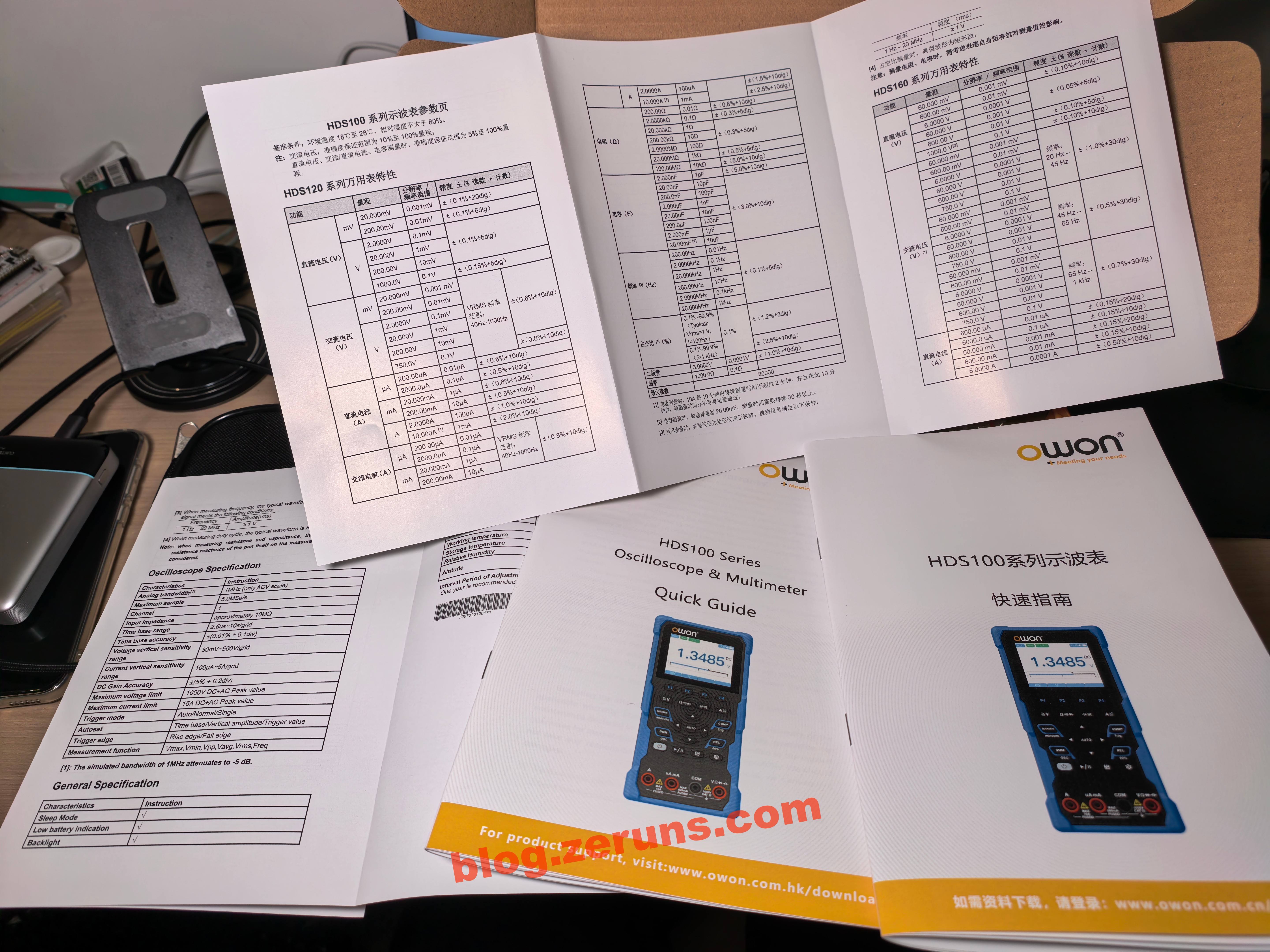
Under the case, there's the user manual.
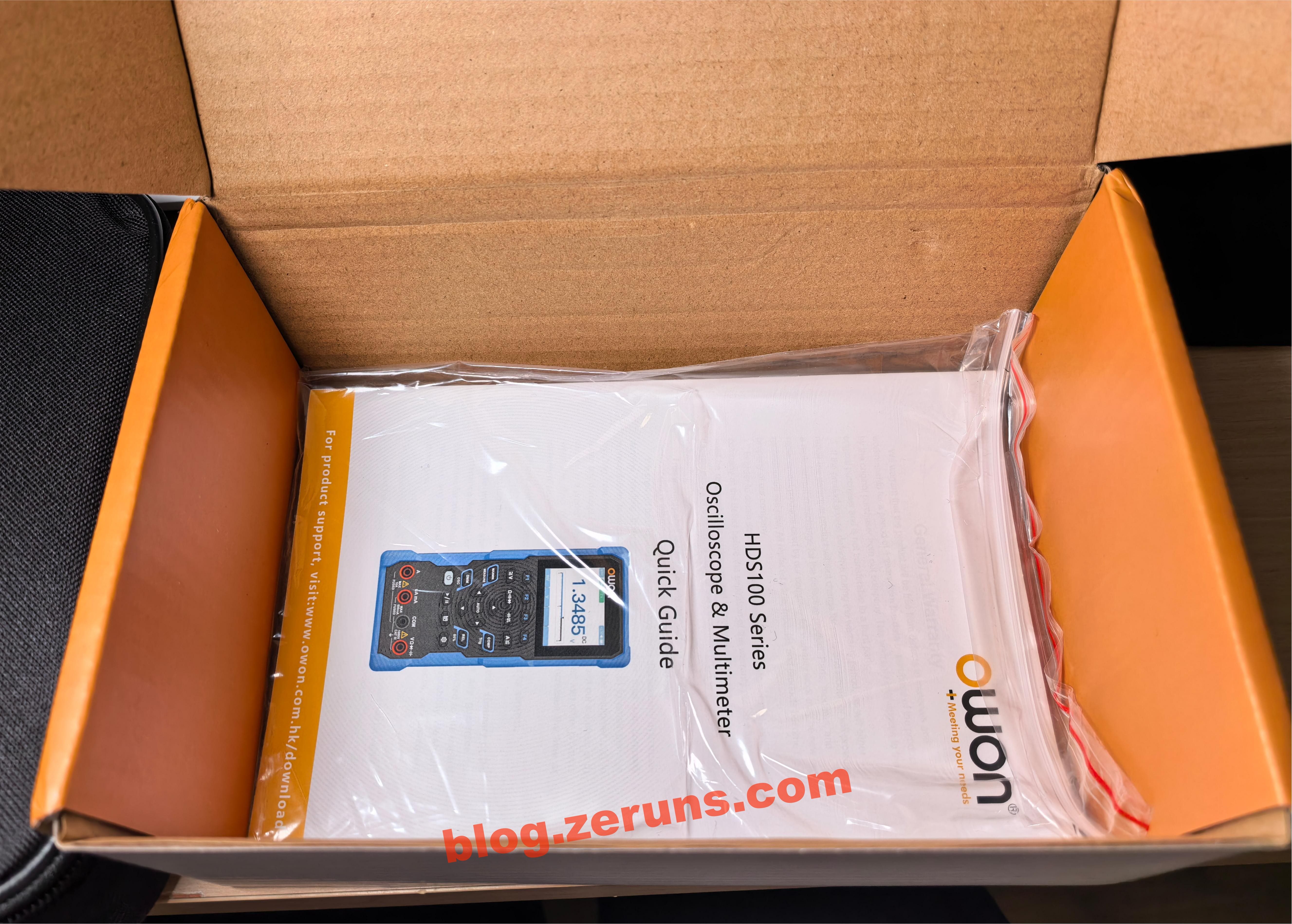
It includes a specification sheet and a quick start guide, both in Chinese and English.
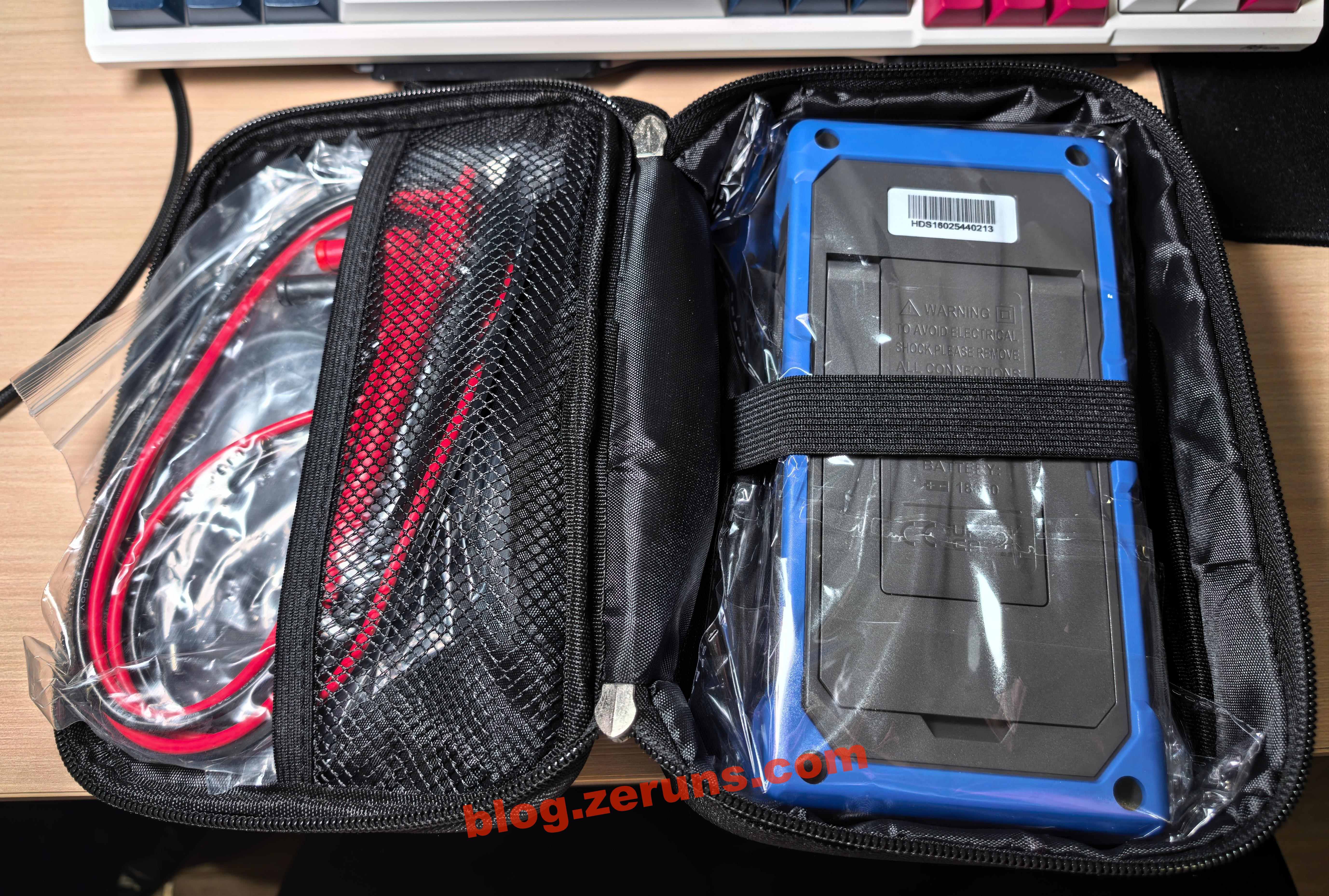
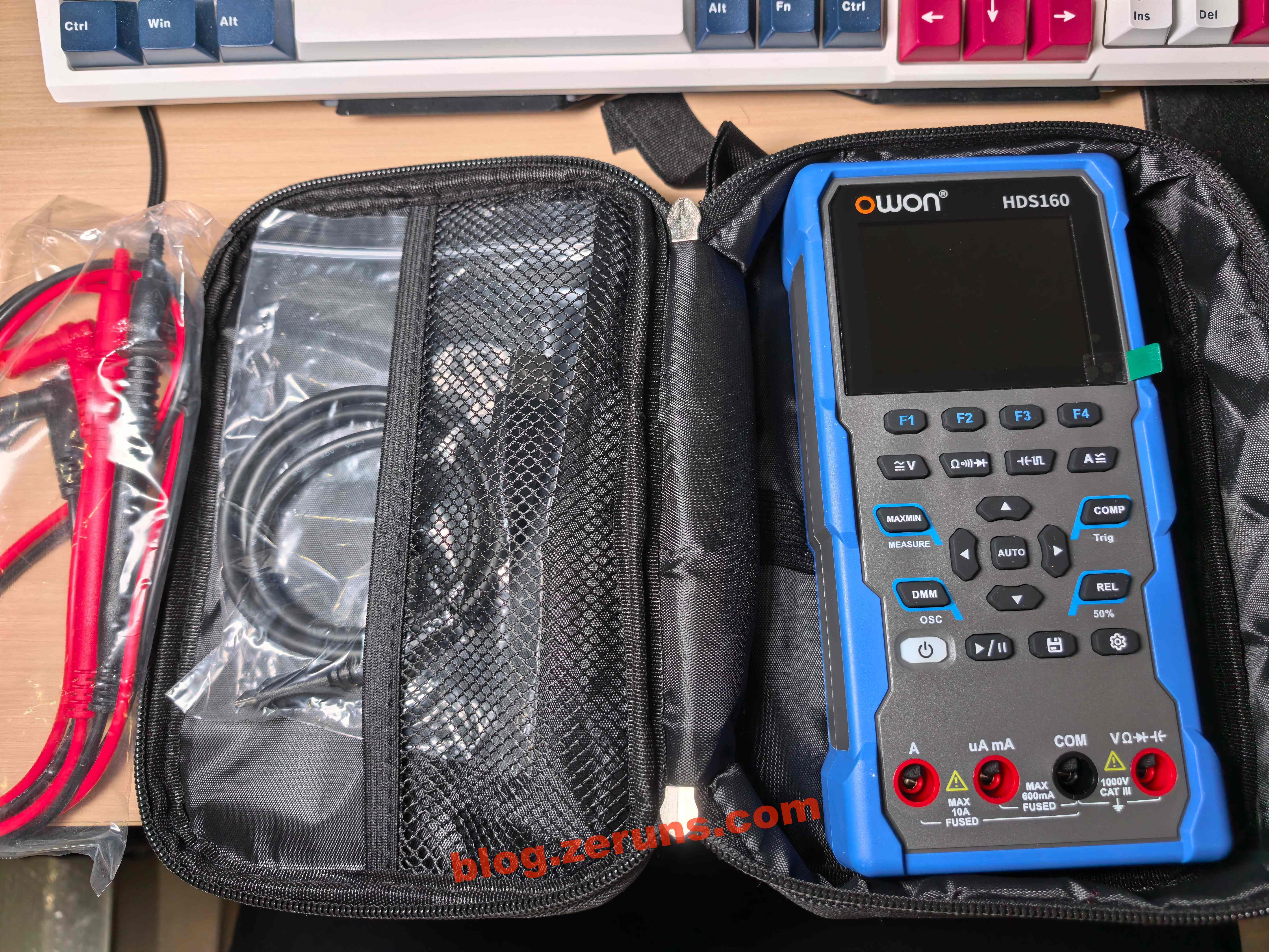
Opening the carrying case, you'll find the multimeter itself, a pair of standard test leads (not ultra‑sharp probes), and a USB Type‑C cable.
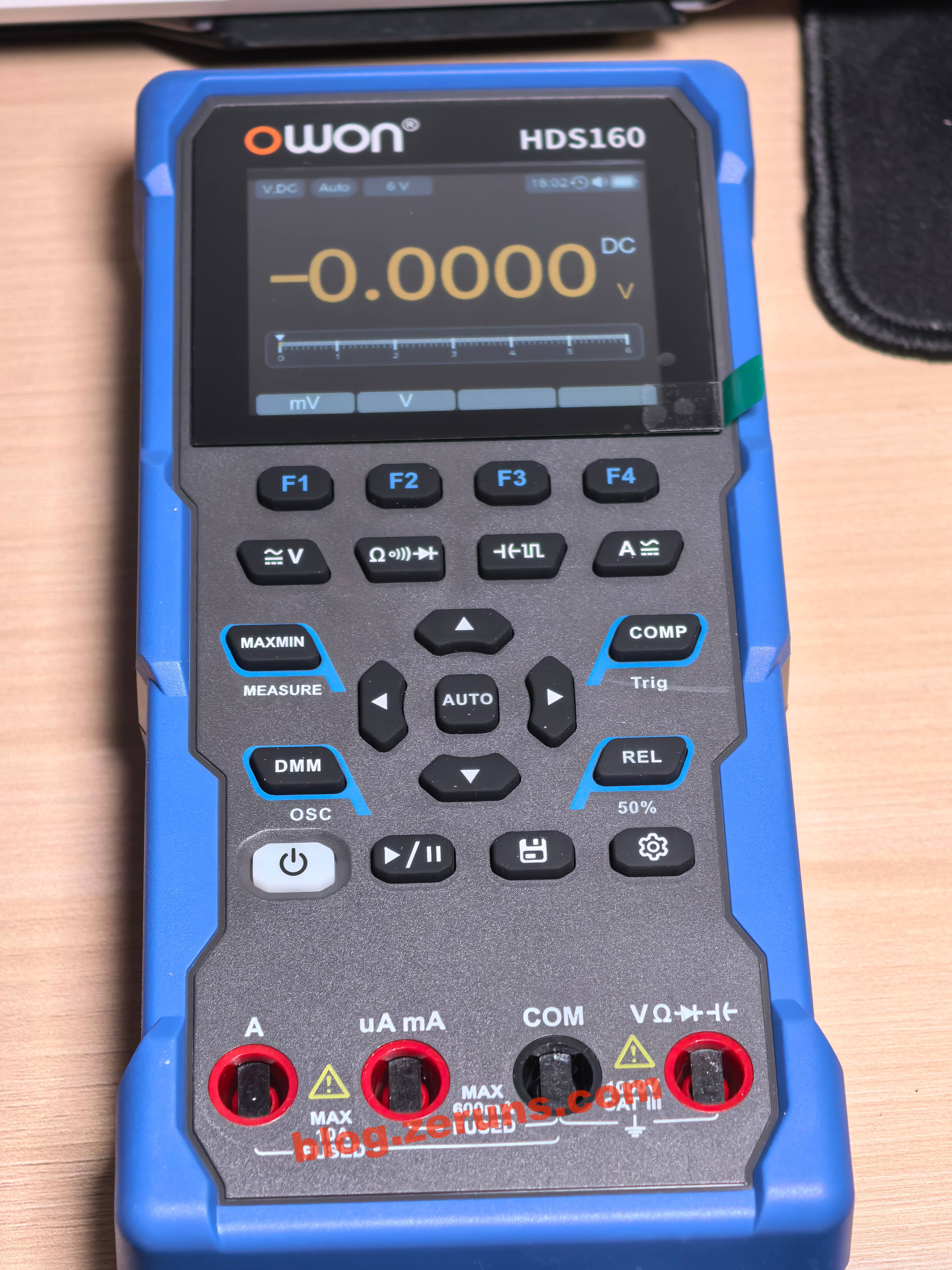
Front view of the multimeter.
Rear view of the multimeter. There's a fold‑out kickstand on the back, allowing it to stand upright.
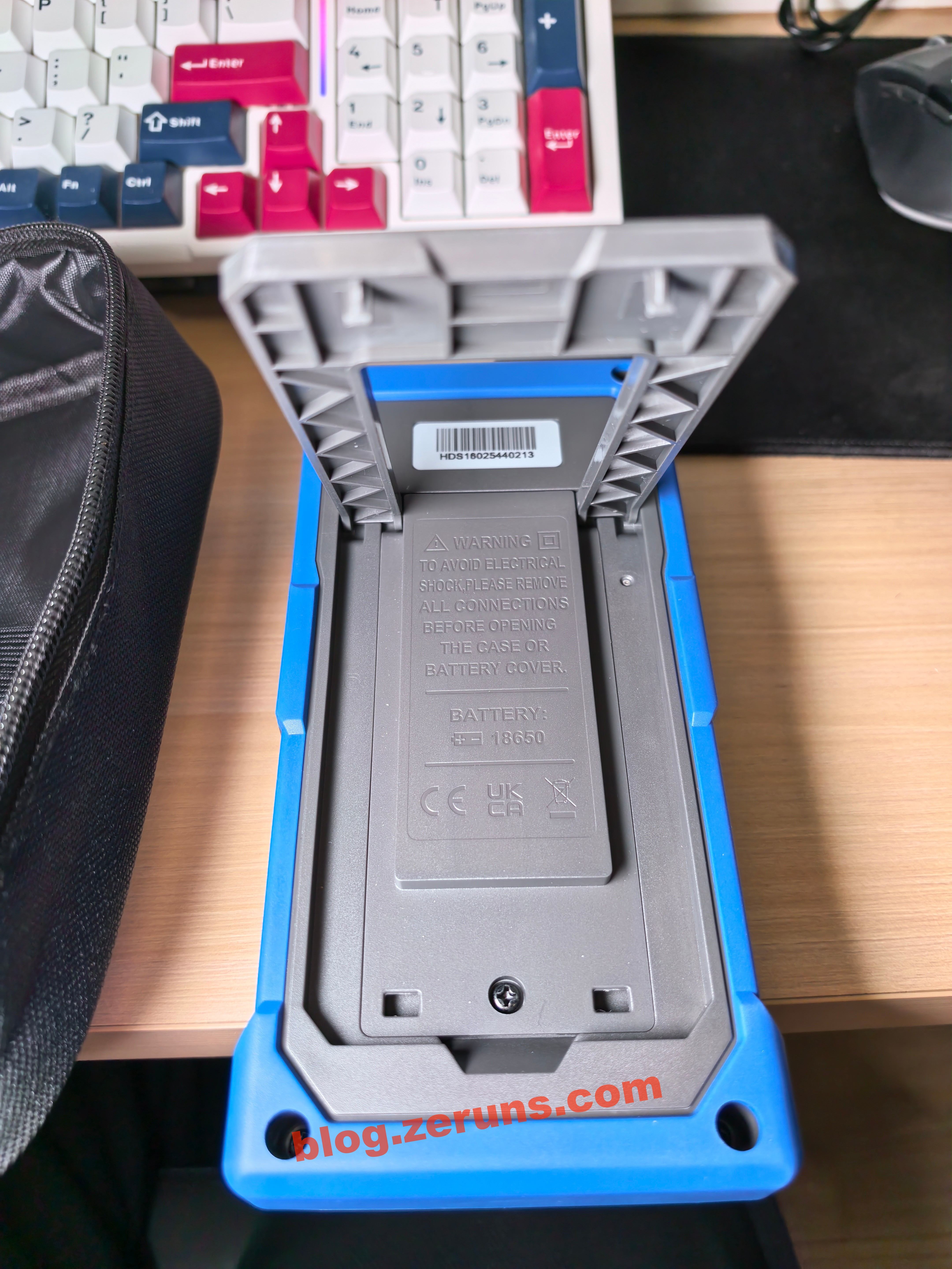
The multimeter standing upright using the kickstand.
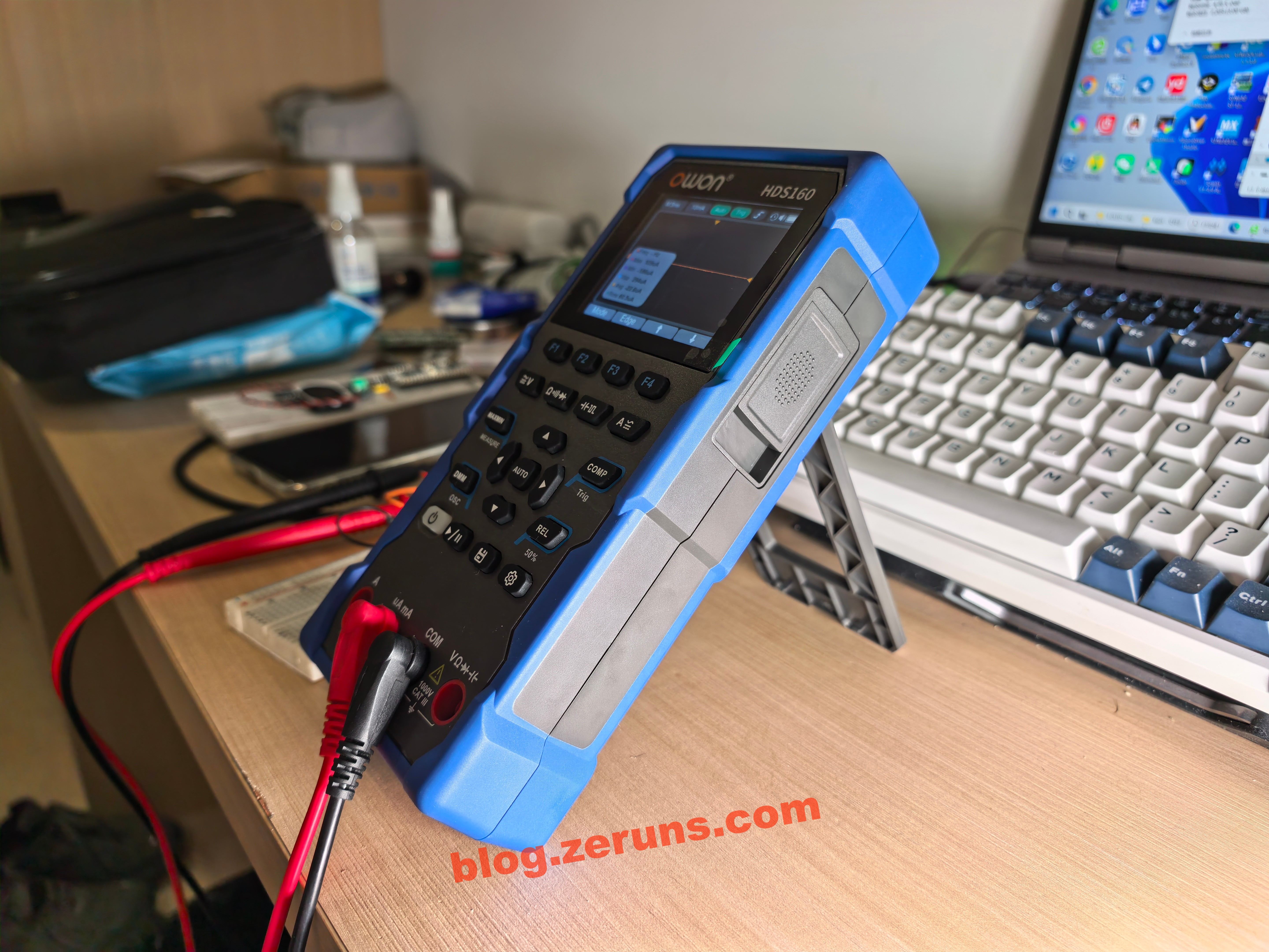
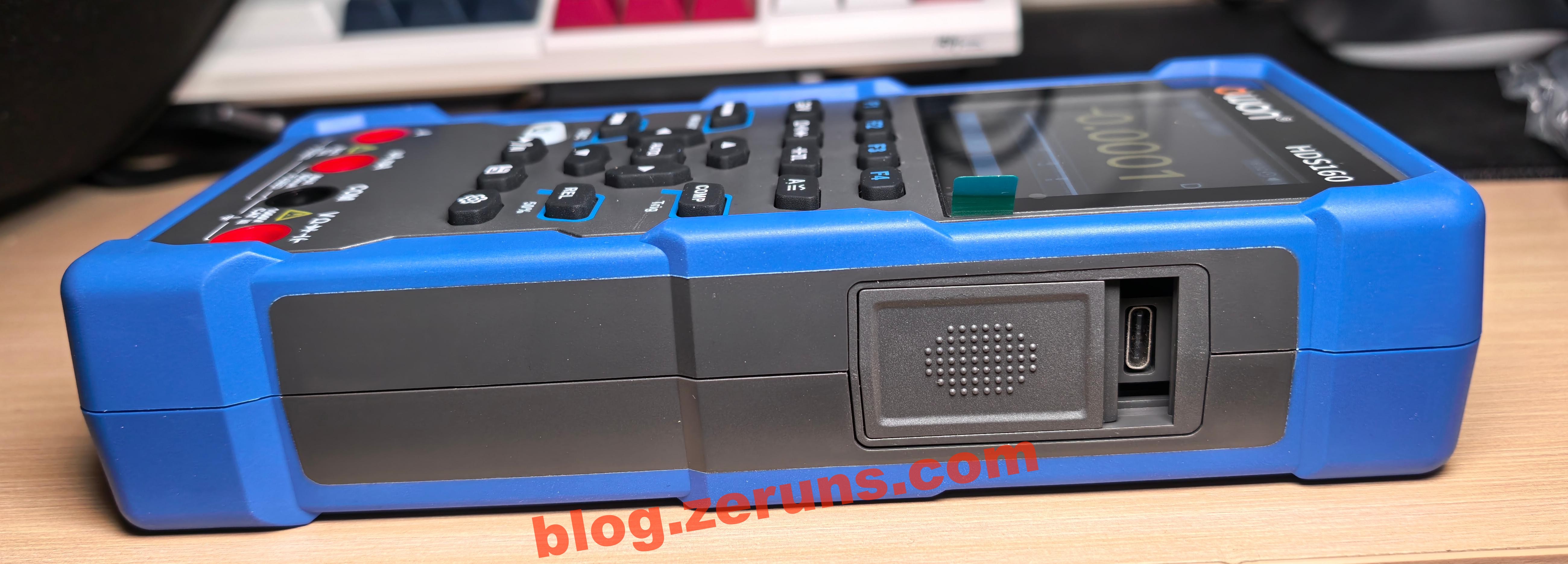
On the side of the multimeter, there's a USB Type‑C port for charging. When connected to a PC, it shows up as a virtual USB flash drive, allowing you to directly copy oscilloscope screenshots. The Type‑C port looks slightly crooked (you'll see why in the teardown—it seems to be misaligned during soldering). There's also a small sliding cover here: when it's slid down for charging, it blocks the probe input jacks, preventing the meter from being used while charging.
Quick Review
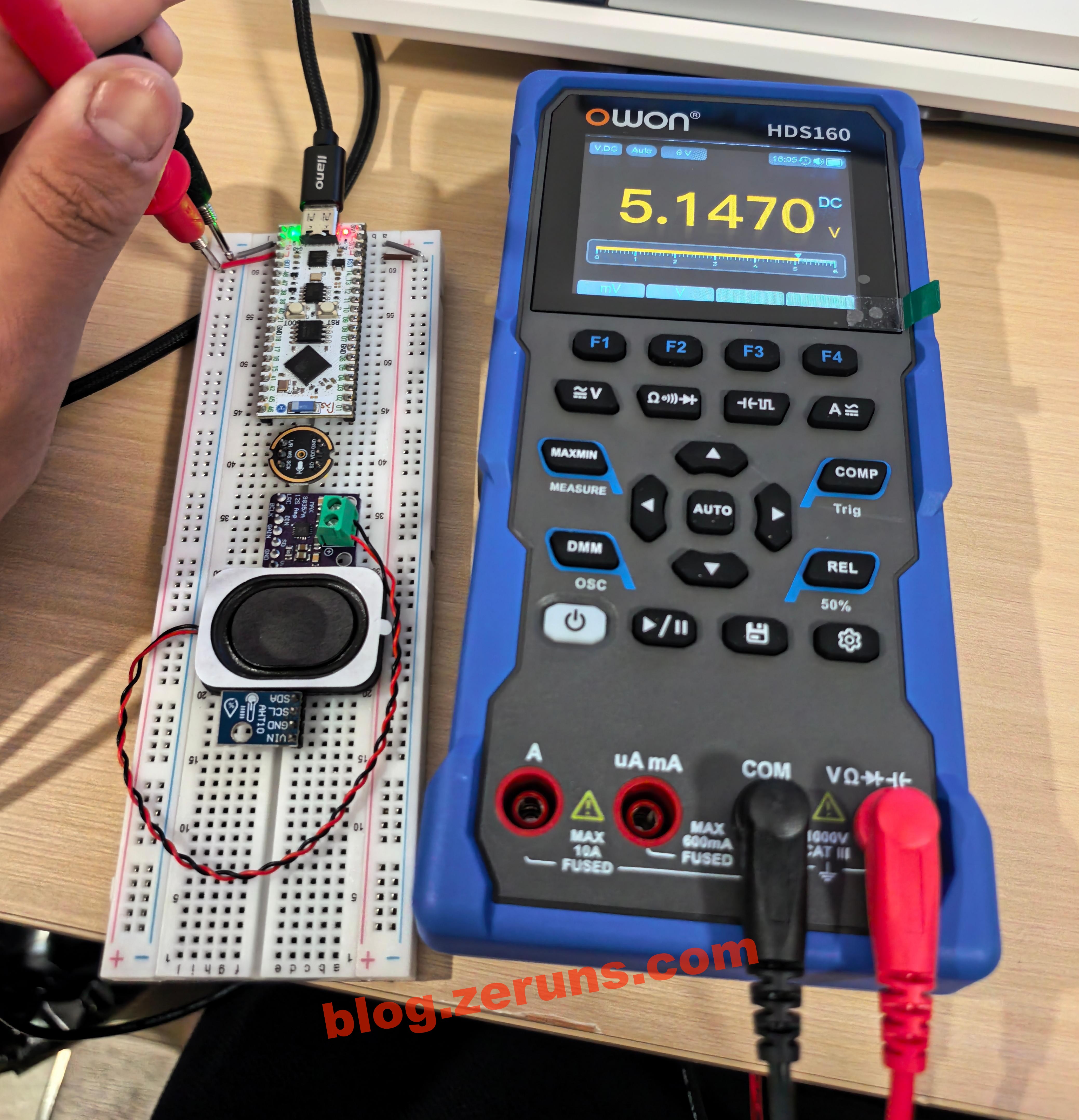
Long‑press the power button to turn it on. By default, it powers up in DC voltage mode of the multimeter, using a dark theme. Press F1 to switch to the millivolt range. The probe jacks at the bottom are blocked here because the charging port cover has been slid down.
Measuring the voltage of a computer USB port: 5.147 V. Since I'm currently in Shenzhen and didn't bring much test equipment with me, I can't really evaluate its accuracy in detail.
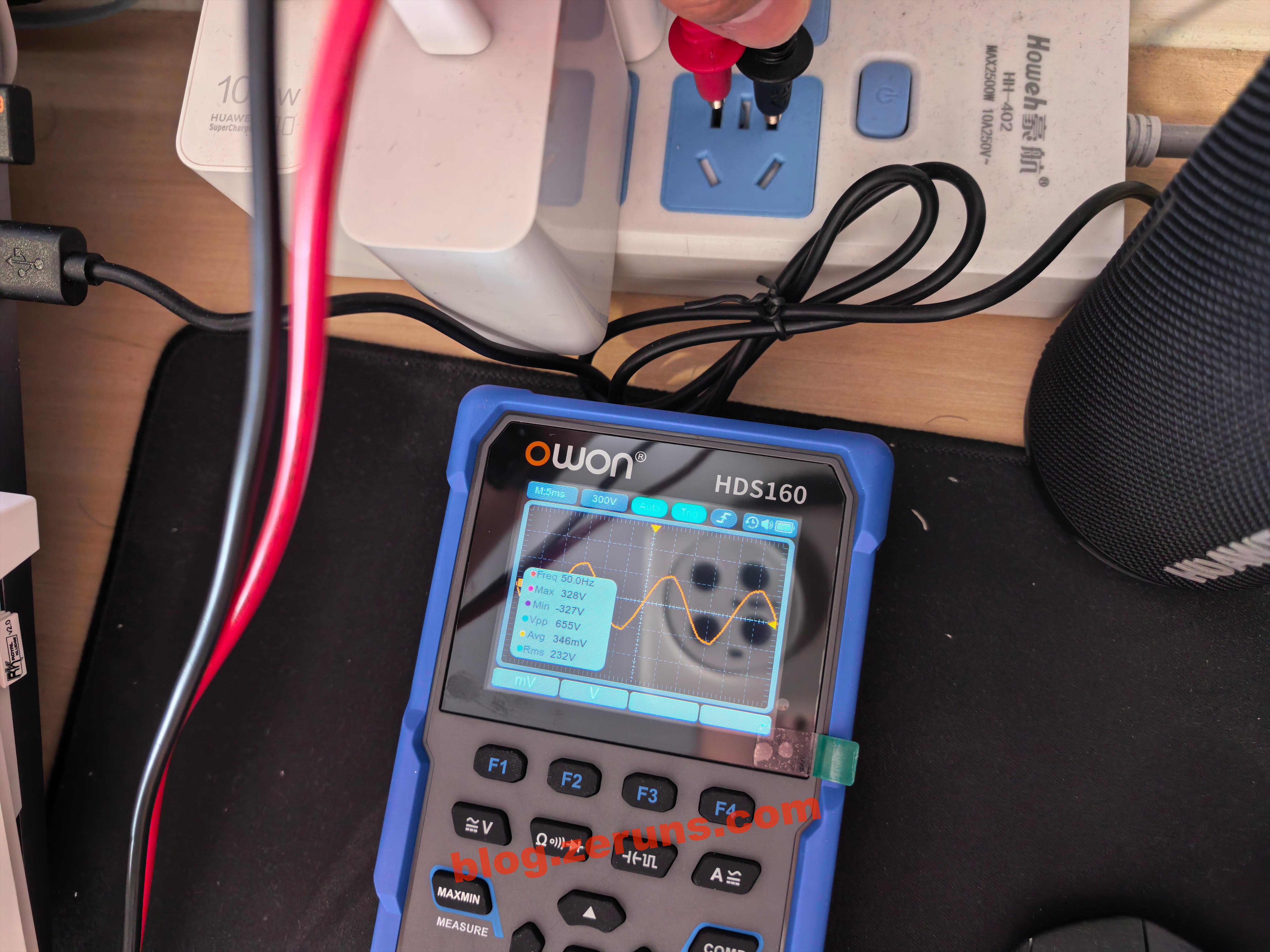
Press the DMM key to enter oscilloscope mode. Plugging the probes directly into a mains outlet, it measures the AC mains waveform: 50 Hz frequency, 328 V peak, and 232 V RMS.
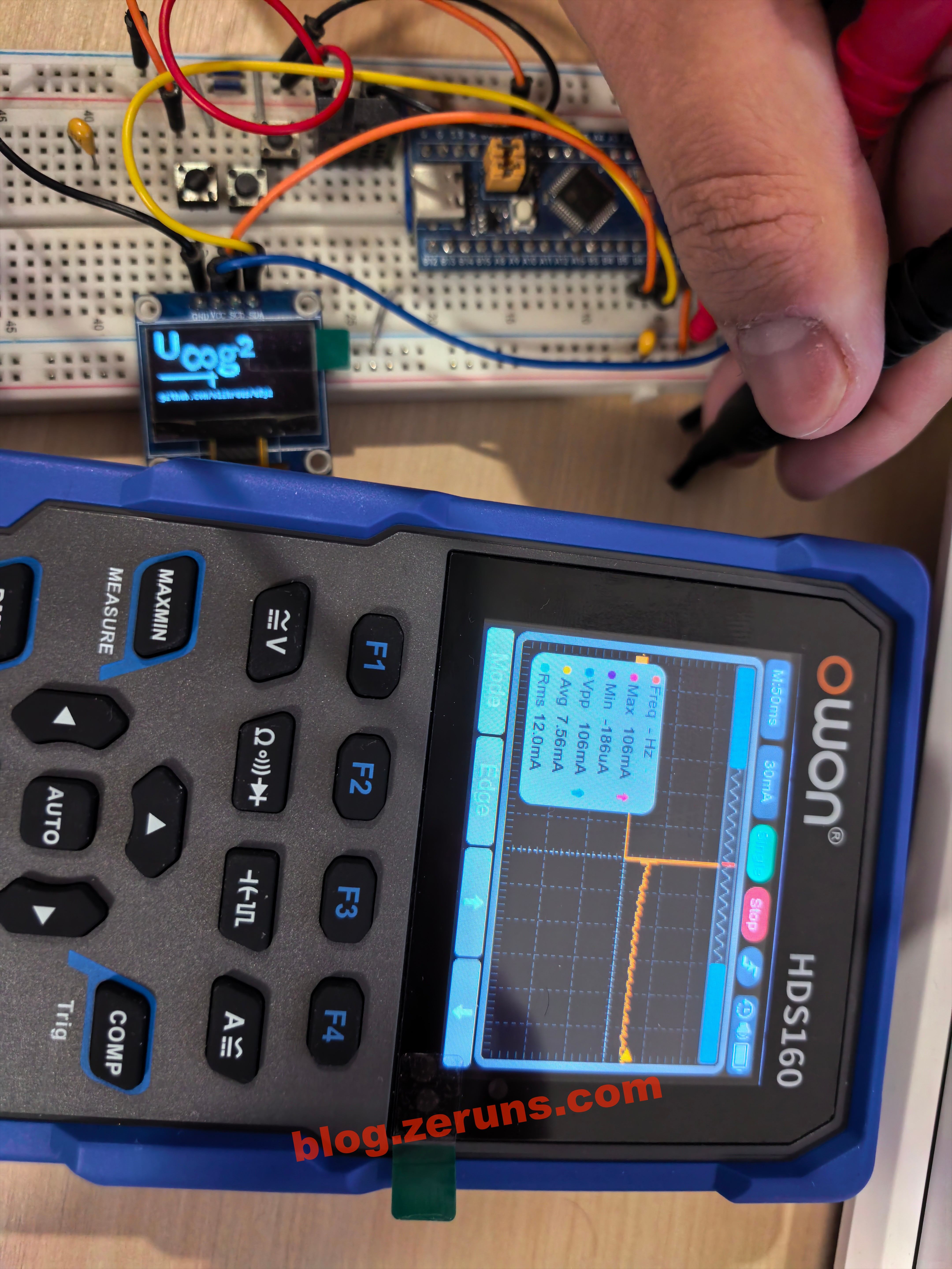
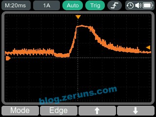
Insert the probes into the current input jack, and the meter automatically switches to the current range. In oscilloscope mode, you can switch to single‑shot trigger and capture the inrush current waveform when powering up an STM32F103 microcontroller board with an OLED display. The peak current measured is 106 mA.
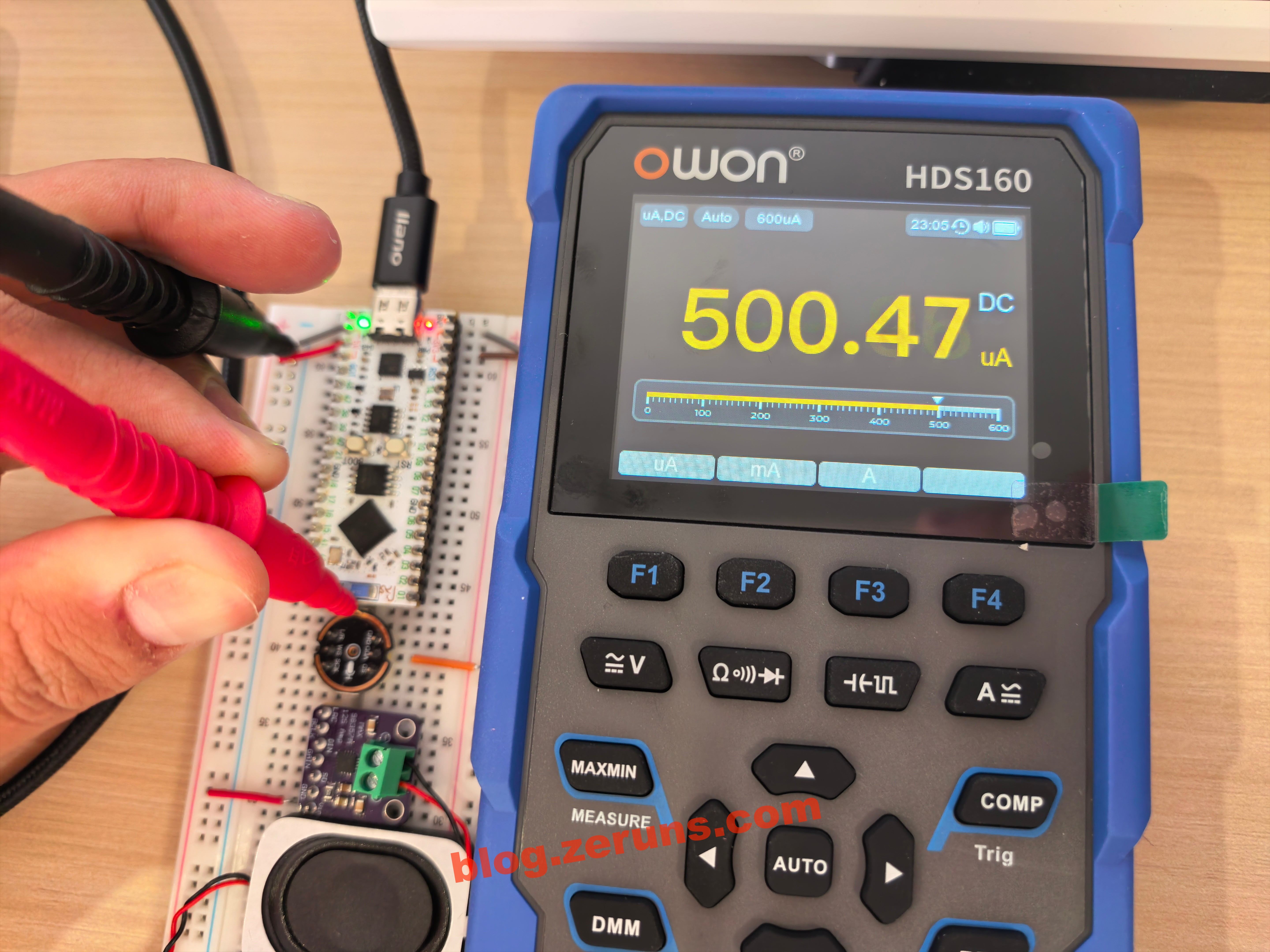
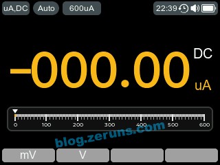
Measuring the operating current of an INMP441 digital microphone (powered but not communicating). The images below show the multimeter mode and oscilloscope mode respectively, with an RMS current of around 500 μA.

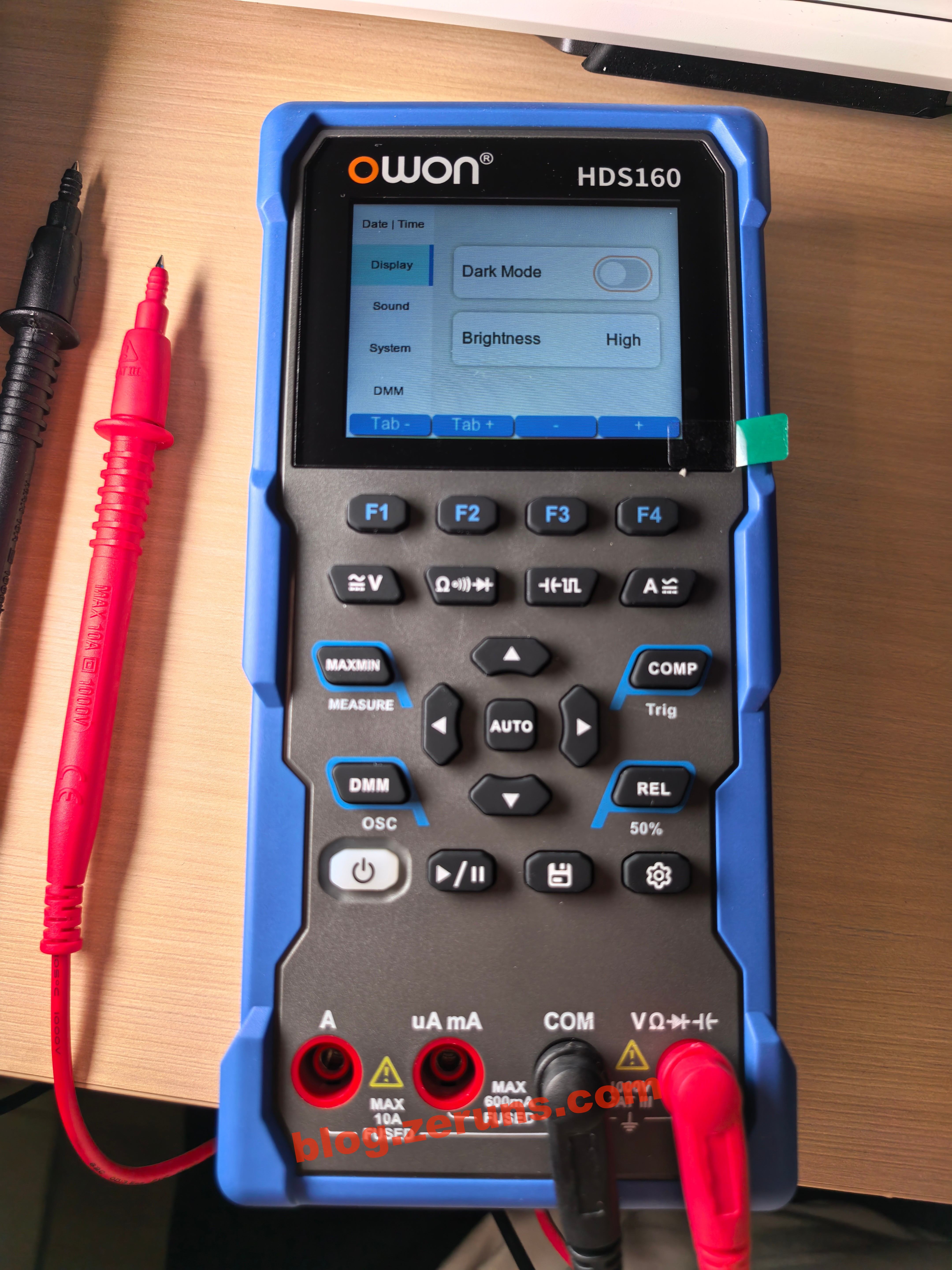
In the settings menu, you can switch between light and dark themes. The light theme uses a white background. You can also set the system time, enable/disable the buzzer and adjust its volume, set the auto power‑off time (up to 30 minutes), and configure the resistance threshold for the buzzer/continuity mode. Since there's no RTC backup battery, the time resets whenever the battery is removed, so the clock function isn't particularly useful.
Judging from the UI style, it's likely built using the LVGL graphics library.
LVGL project template based on STM32F407 (MSP3526 display), including both FreeRTOS and bare‑metal versions: https://blog.zeruns.com/archives/788.html
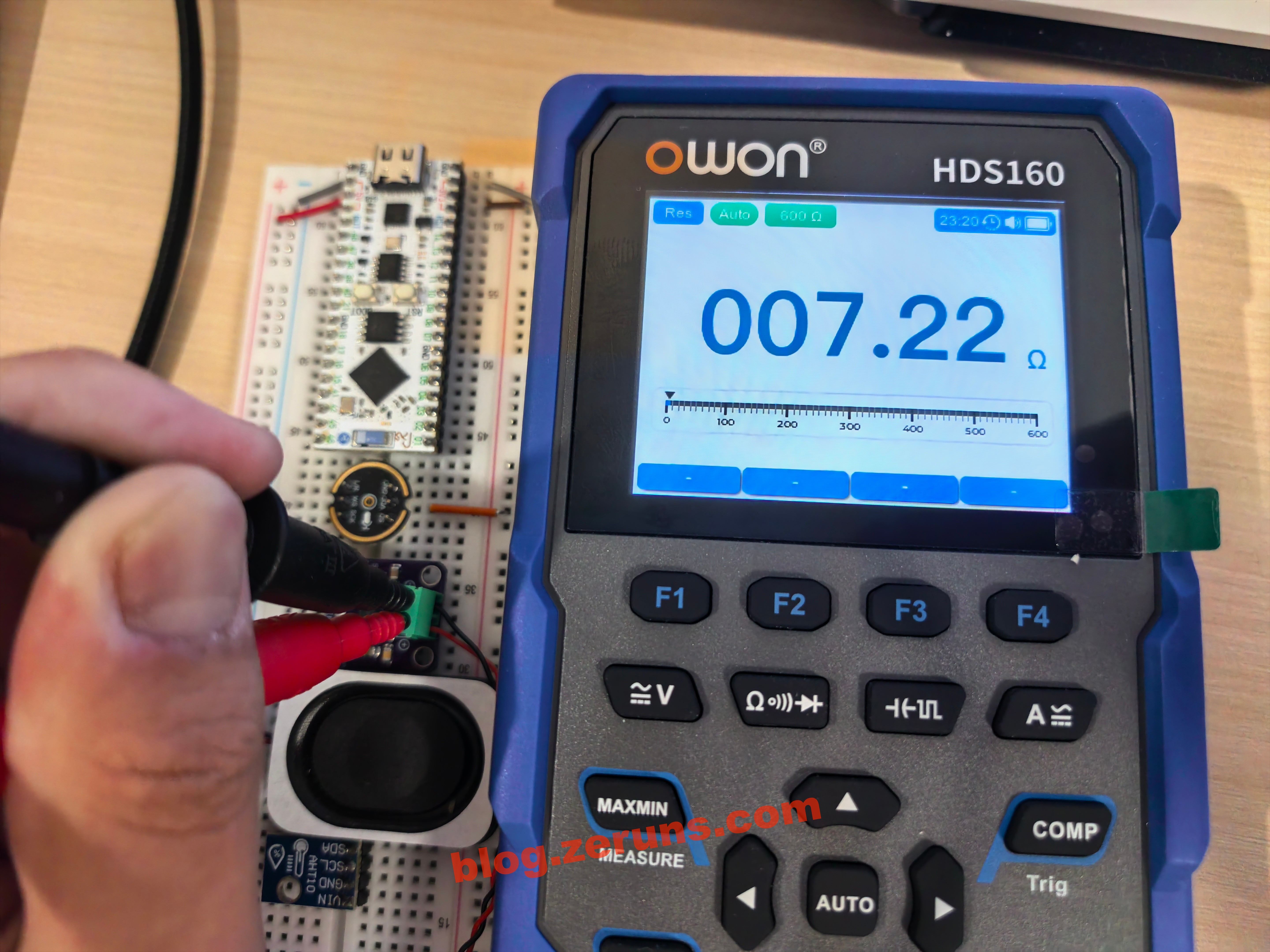
Measuring the resistance of a speaker: 7.22 Ω.
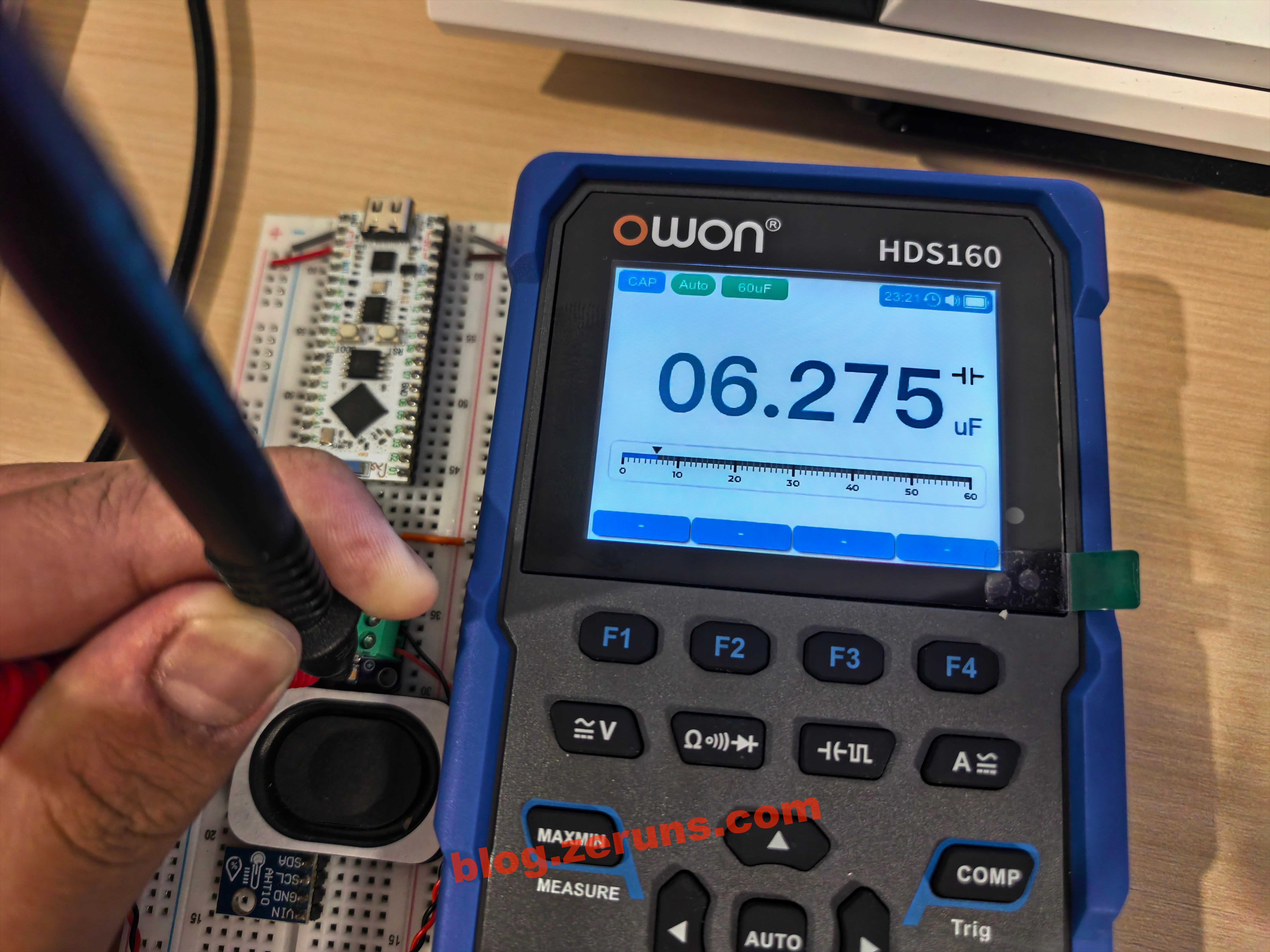
Capacitance measurement.
In oscilloscope mode, measuring the audio output waveform of a MAX98357A. It appears to be PDM‑modulated.

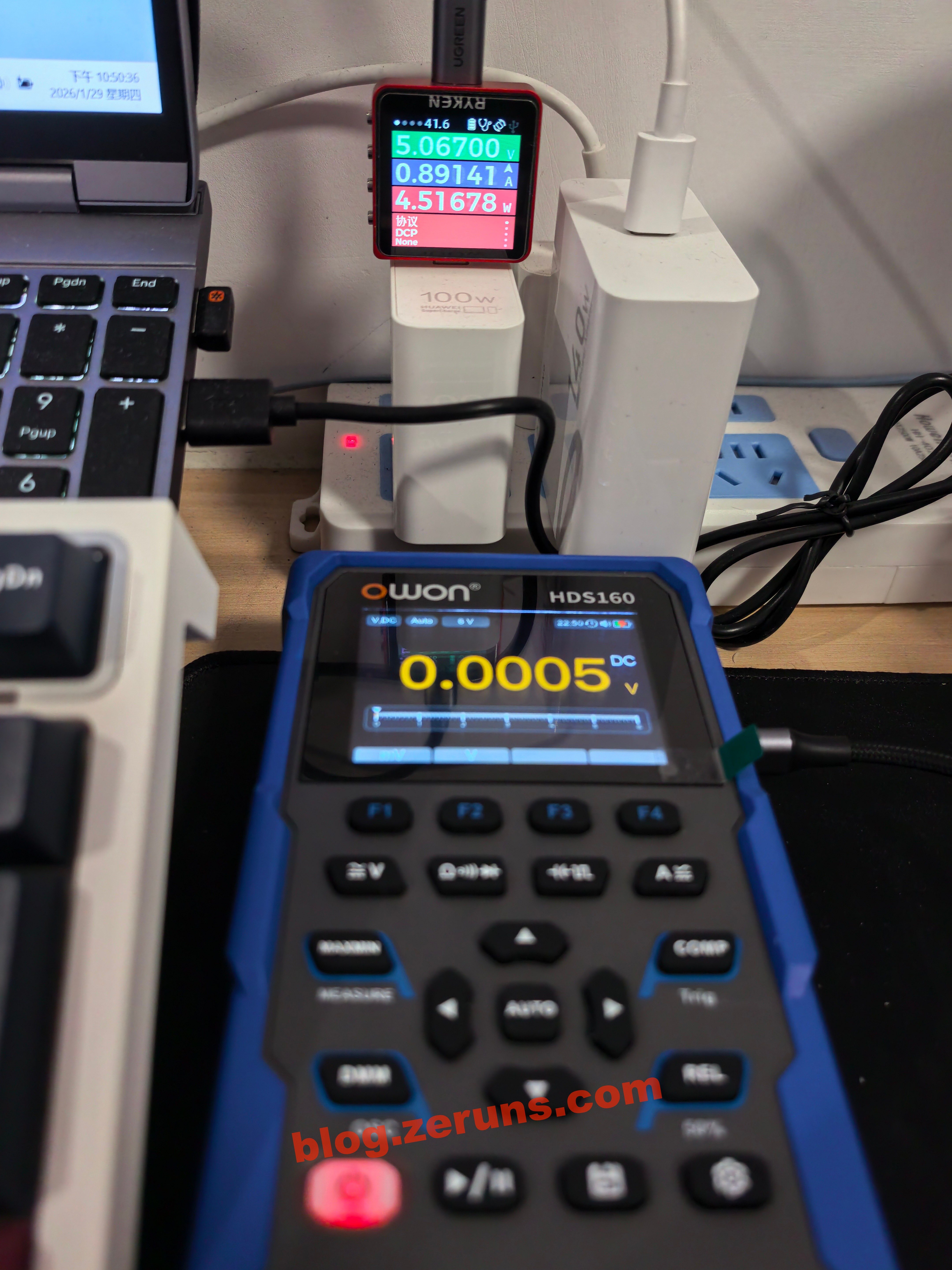
The charging power of the multimeter is around 4.5 W.
There's also a screenshot function. Simply connect the Type‑C port to a computer and you can copy the screenshots directly. It's quite convenient, but one downside is that oscilloscope screenshots don't include grid lines, which makes it harder to read exact values.
Teardown
Remove the screw on the rear kickstand to take it off, and you'll see the 18650 battery and two fuses. The fuse under the battery is rated at 10 A, while the one next to the battery is rated at 600 mA, likely for the milliamp current range.
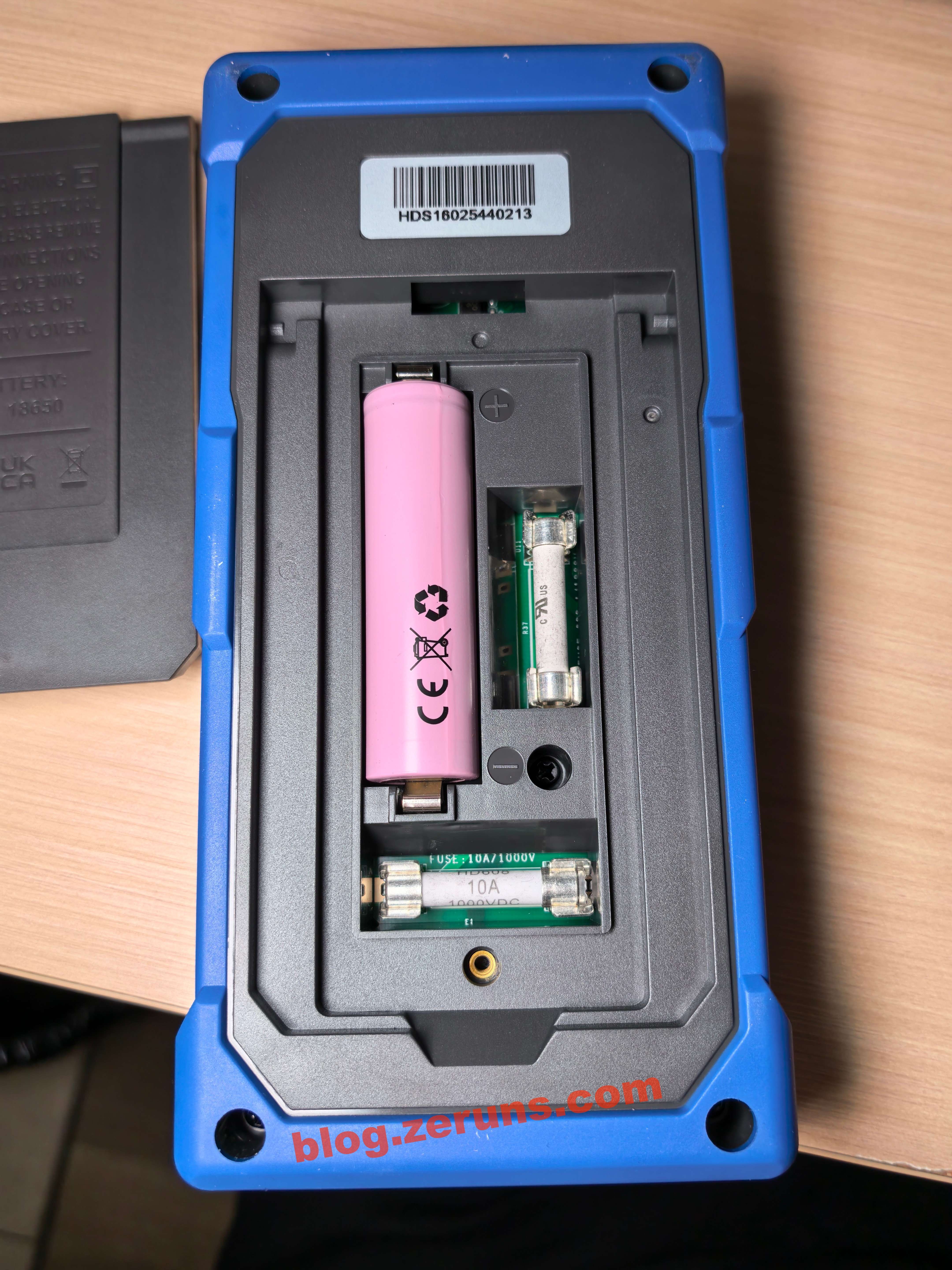
The 18650 battery is labeled: 3.7 V, 2600 mAh, 9.62 Wh.
The battery brand is ROOFER, model: 1NR18650‑2600A.

Remove the screws around the perimeter to take off the bottom shell of the multimeter.

The main MCU is an HC32F460PETB, a 32‑bit industrial‑grade MCU from Huada Semiconductor, based on the Cortex‑M4 core (with FPU/DSP). It runs at up to 200 MHz and features 512 KB Flash and 192 KB SRAM in an LQFP100 package. The crystal oscillator next to it is 8 MHz.
I suspect the oscilloscope function is implemented using the MCU's internal ADCs. This MCU has two independent 12‑bit 2 MSPS ADCs and one programmable gain amplifier (PGA).

The multimeter front‑end chip is the HY3131, a high‑precision multimeter analog front‑end from HYCON Technology. It supports 50,000 counts, integrates a 24bit Σ‑Δ ADC, and includes true‑RMS, frequency measurement, and peak hold functions. It communicates via SPI and comes in an LQFP48 package.
According to AI, multimeter manufacturers often use software algorithms, range calibration, and optimized external circuitry to make this chip achieve a display close to 60,000 counts, allowing them to claim 60,000‑count resolution in product marketing.
To the right of the multimeter chip is an 8‑pin device marked MAX6006AESA. This is an ADI (formerly Maxim) grade‑A ultra‑low‑power shunt precision voltage reference, with a fixed 1.25 V output, ±0.2% initial accuracy, ±30 ppm/°C temperature drift, and operating current below 1 μA. It comes in an 8‑pin NSOIC package and requires no external capacitors, making it suitable for low‑power precision measurement, portable instruments, and ADC/DAC reference applications.

Next to the 600 mA fuse is a TB10S bridge rectifier. I'm not sure what it's used for—if anyone knows, feel free to share in the comments.
Nearby is a relay marked B3GB4.5Z, a Fujitsu bistable latching ultra‑thin signal relay. It has a 4.5 VDC / 100 mW coil, DPDT (2C) contacts, rated at 1 A / 30 VDC and 0.3 A / 125 VAC. It's an SMD package measuring 7.2 × 10.6 × 5.25 mm, weighs 0.85 g, offers good high‑frequency performance, 1500 VAC dielectric strength, and is RoHS compliant—well suited for high‑density signal switching applications.

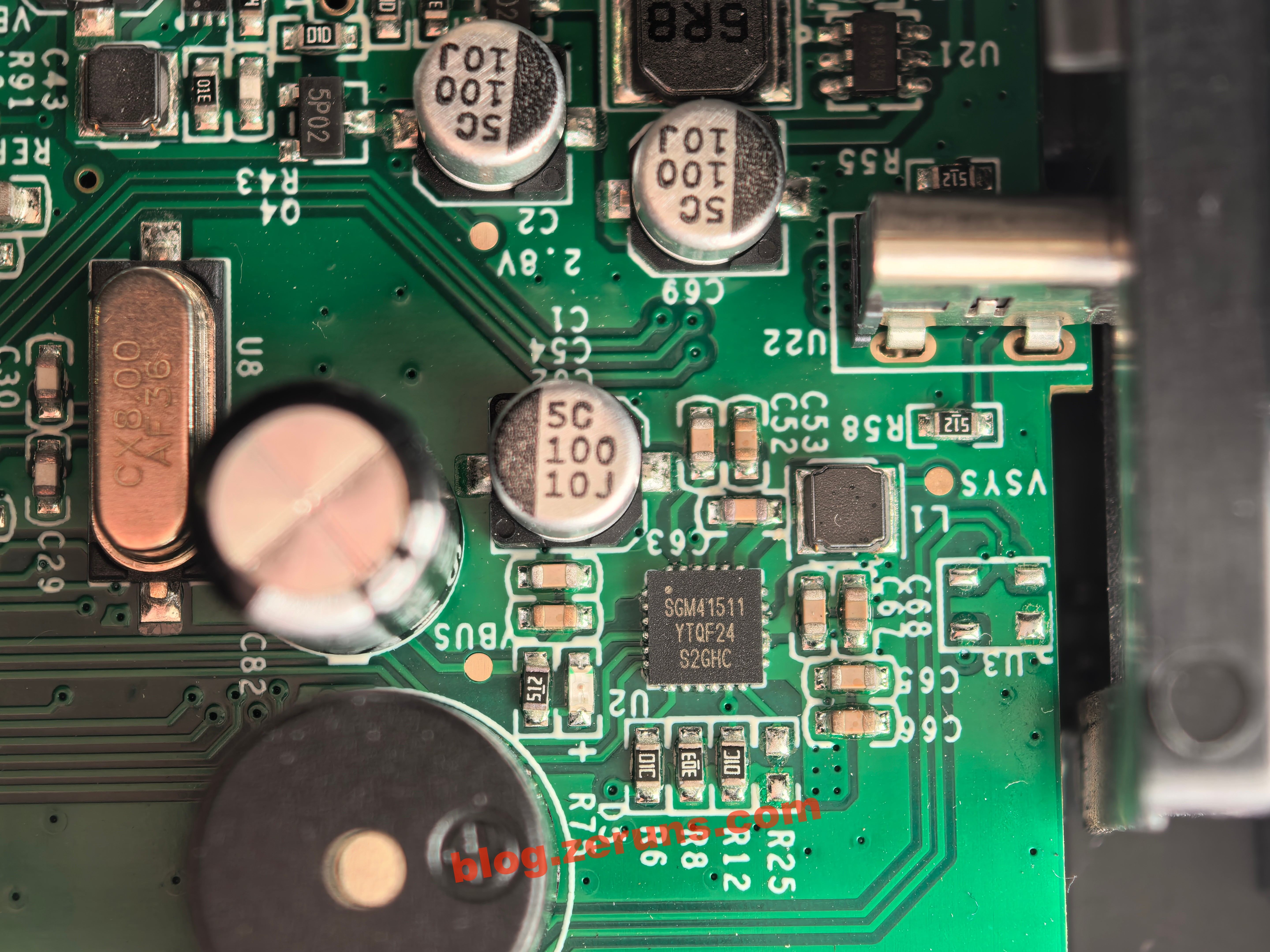
The chip next to the Type‑C port is marked SGM41511. This is a programmable 3 A single‑cell Li‑ion battery charger with NVDC power‑path management from SG Micro. It integrates four power switches and converters, supports USB/OTG, wide input voltage, and DPM (Dynamic Power Management), and includes JEITA temperature control, over‑voltage, over‑current, and thermal protection. It comes in a TQFN‑4 × 4‑24L package.
According to the datasheet, this chip supports 5 V / 2 A input, but in actual testing the charging current is only about 5 V / 0.8 A. This is likely due to current limiting in the configuration, possibly because the bundled battery doesn't support higher charging currents.
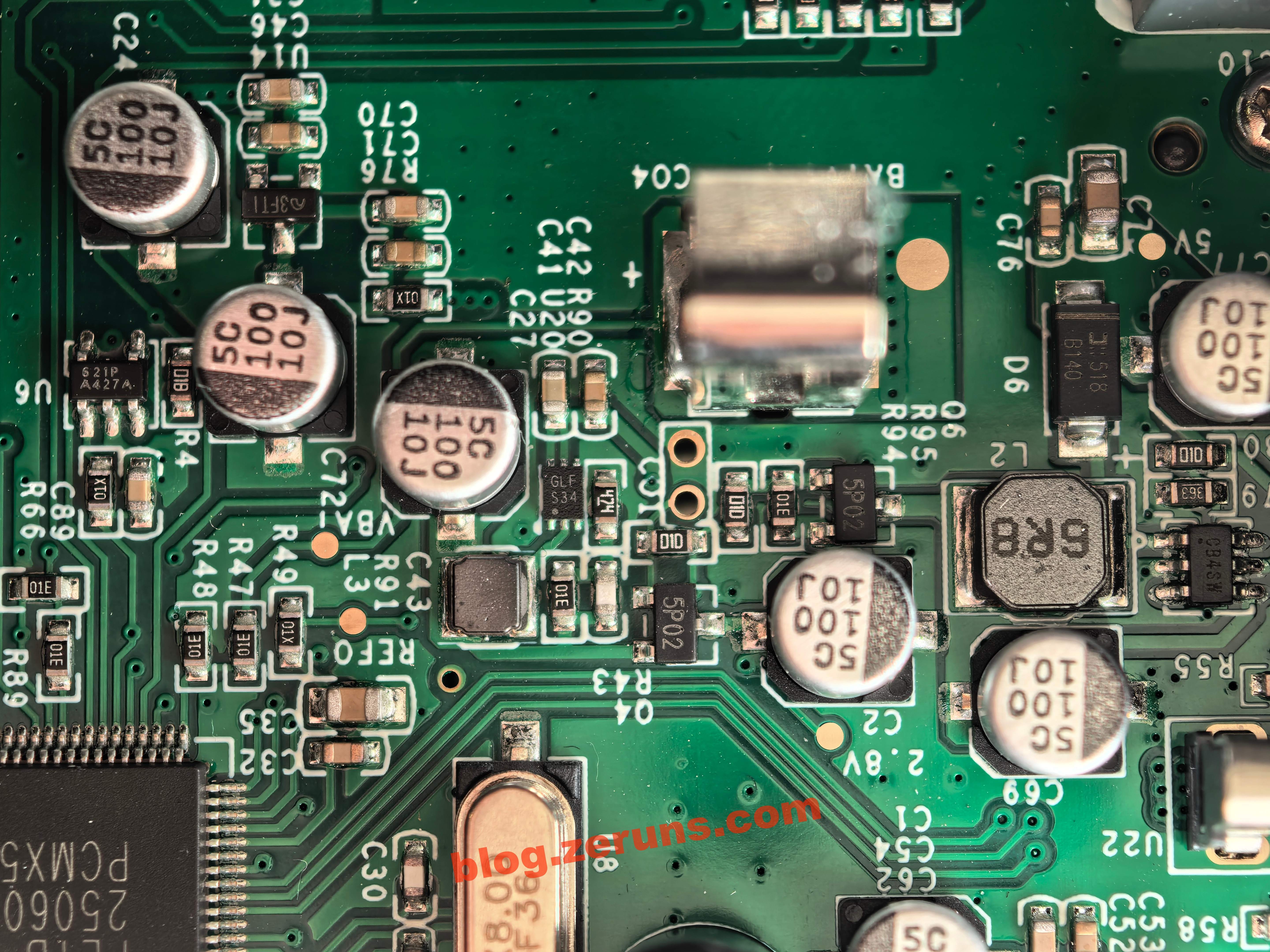
There are several small ICs, a bunch of electrolytic capacitors, and two inductors in this area. This section appears to be the DC‑DC power supply, providing various voltages to different parts of the circuit. The IC markings include S21P‑A427A, 3FT1, GLF‑S34, 5P02, and CB4SW.
After removing the main PCB, you can see the LCD panel on the back, along with a small keypad board. Both are connected via FPC ribbon cables.
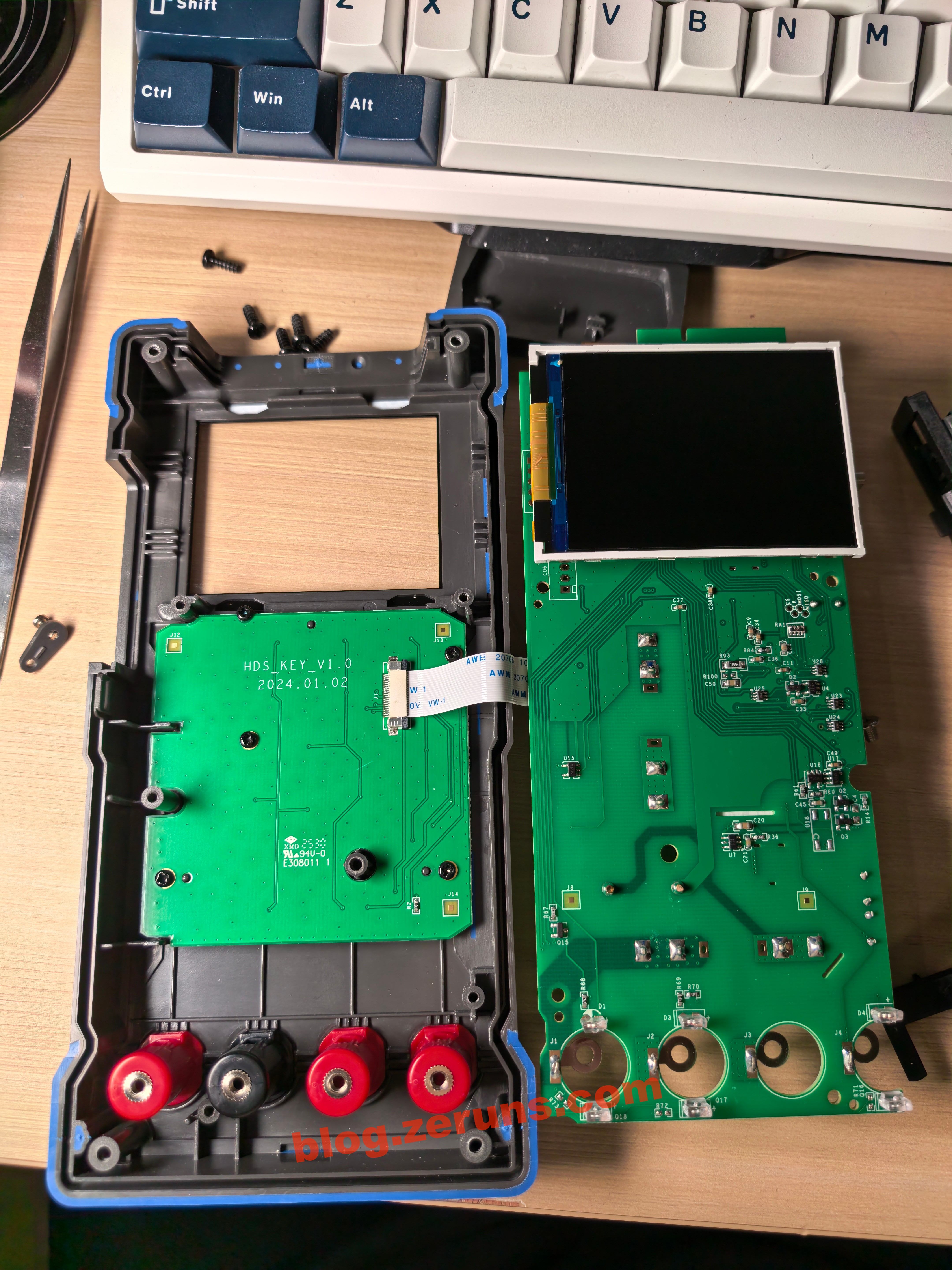
Each of the probe input jacks has what appears to be a pair of infrared components (IR emitter and receiver). These are likely used to detect which jack the probes are inserted into, enabling automatic range switching. It's a pretty neat design.

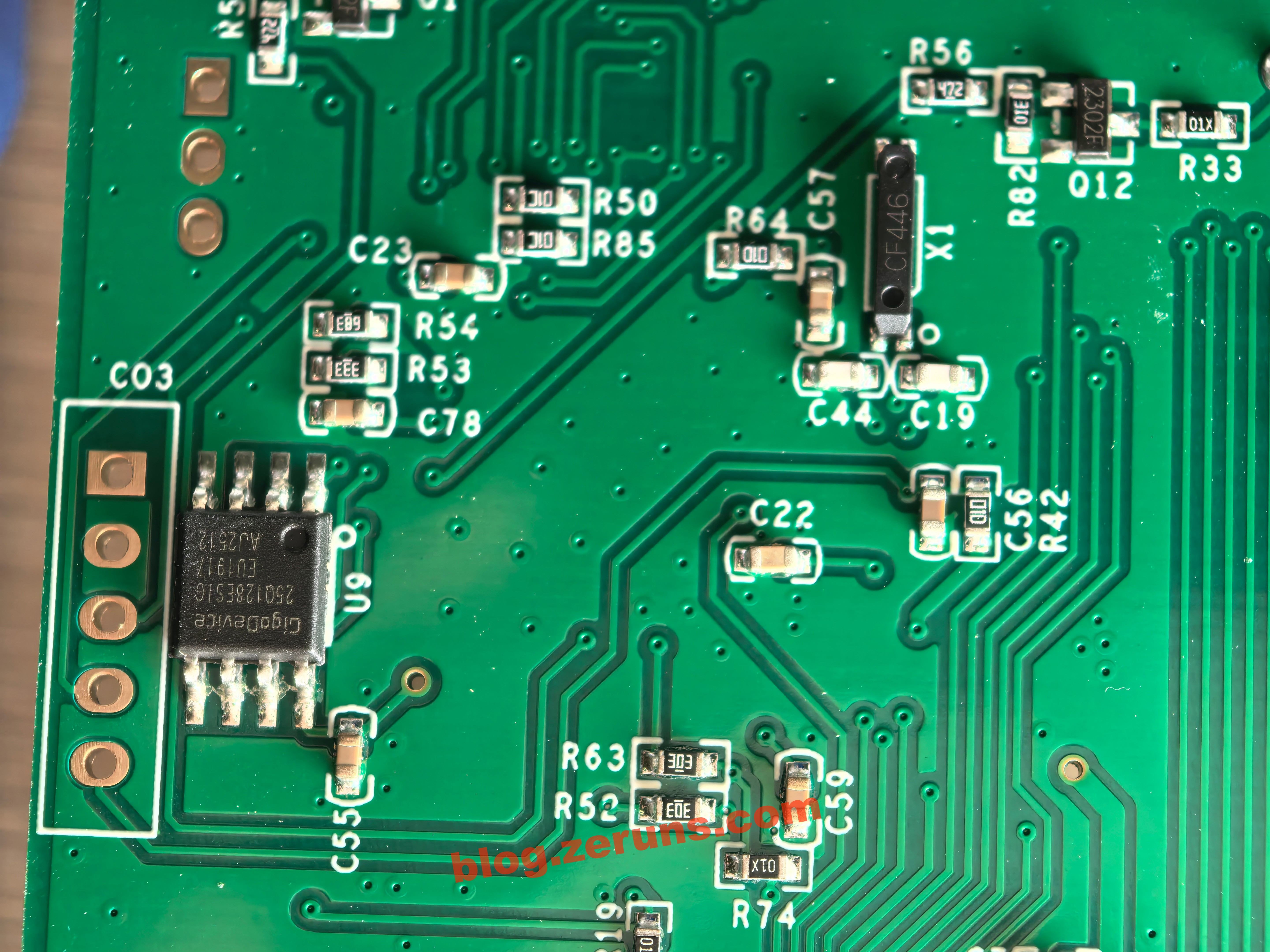
On the back side of the main MCU, there's a GD25Q128ESIG chip. This is a GigaDevice 128‑Mbit (16 MB) SPI Flash memory in an SOP‑8 package, supporting standard, dual, and quad SPI interfaces, with an operating voltage of 2.7–3.6 V. I suspect it's used to store graphical resources for the UI.
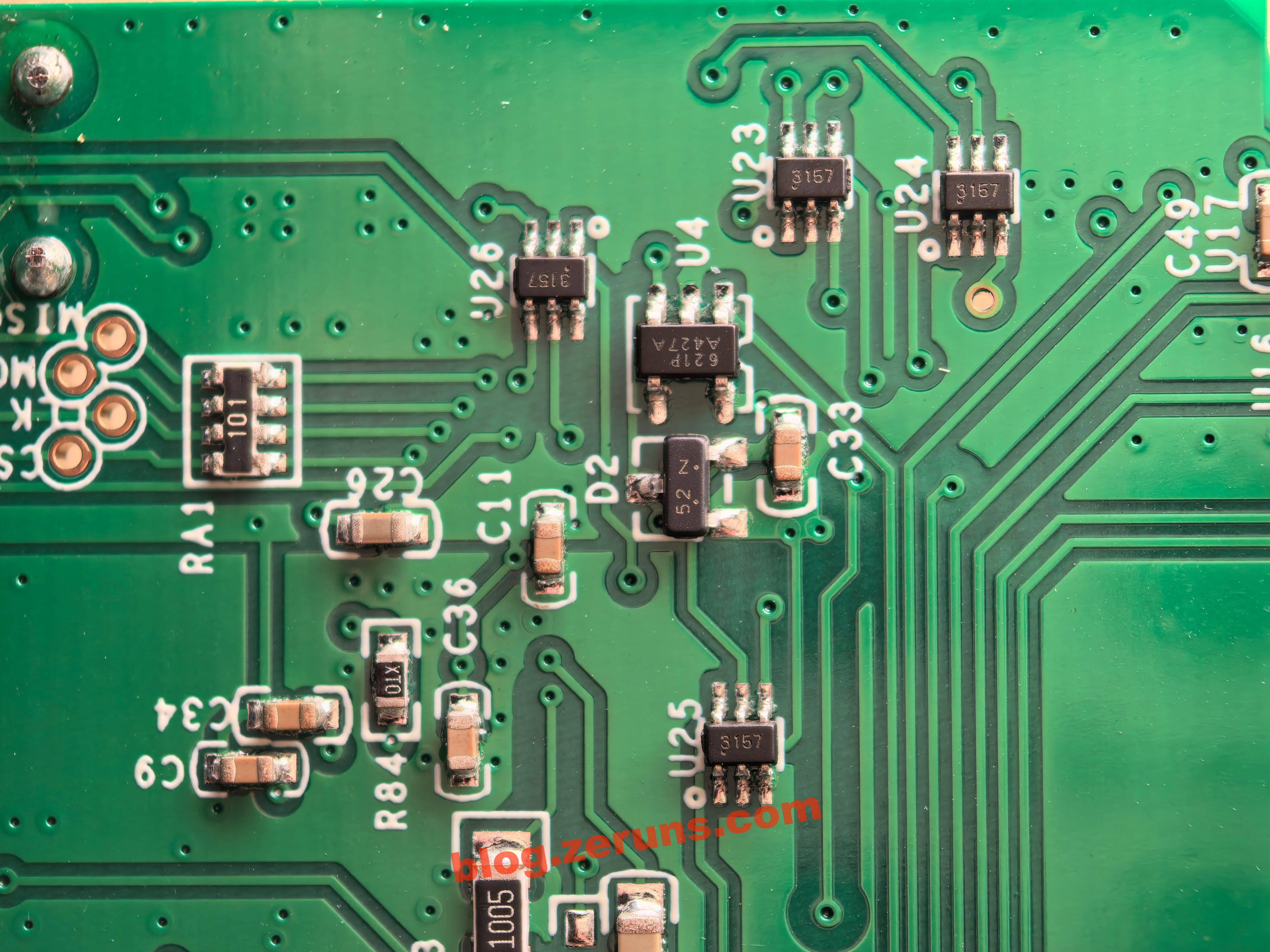
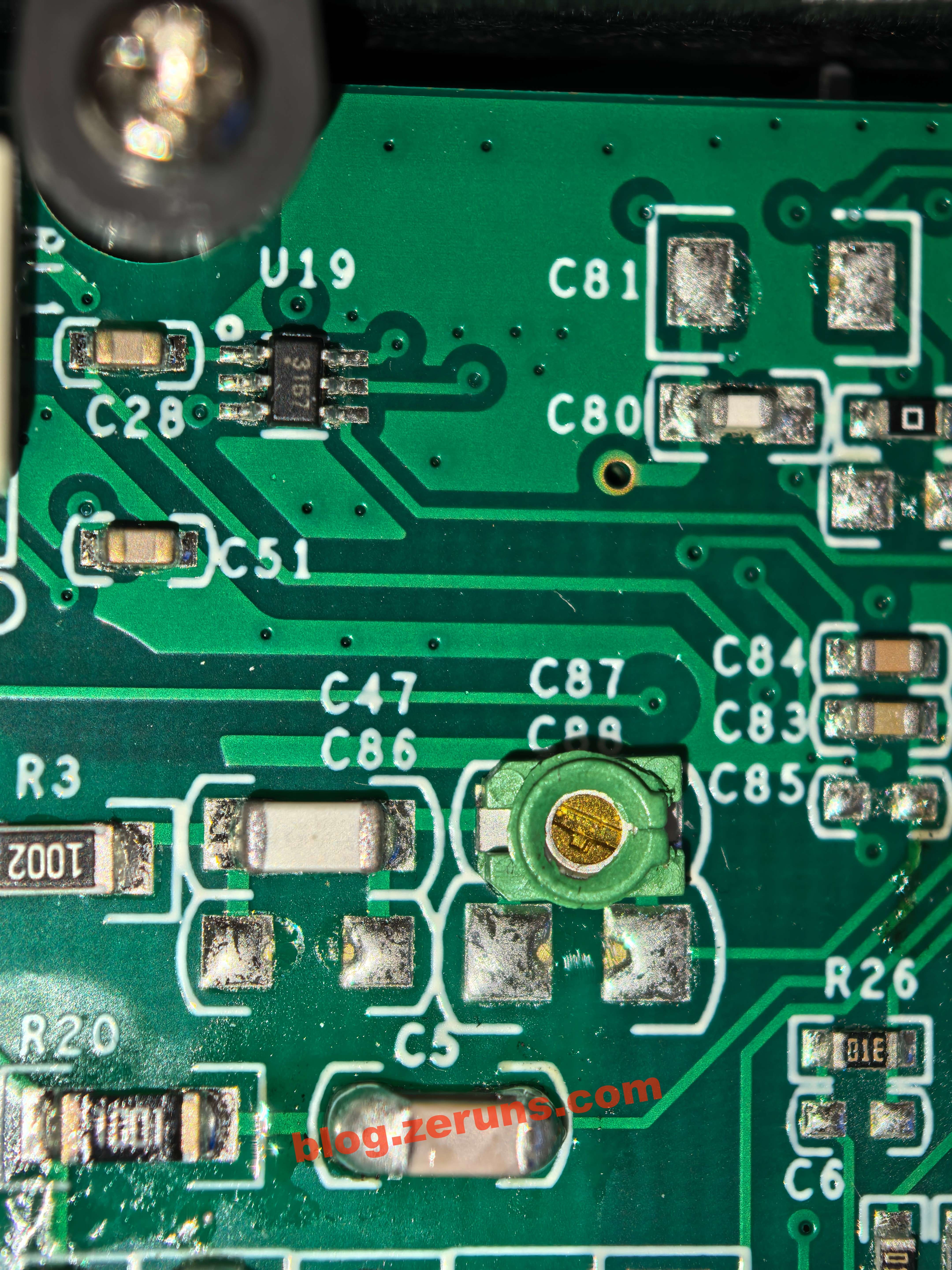
There are also some chips that appear to be used for signal conditioning or analog switching. Their markings include 3157, 621P‑A427A, and 52N.
The small keypad board uses membrane buttons.

There are also several trimmer capacitors, likely used for calibration.
The Type‑C connector is soldered slightly crooked.

Recommended Reading
- High‑value and affordable VPS / cloud server recommendations: https://blog.vpszj.cn/archives/41.html
- Discourse forum setup tutorial: deploying the Discourse open‑source community forum from scratch: https://blog.zeruns.com/archives/919.html
- [Open Source] 24 V 3 A flyback switching power supply (based on UC3842, including circuit design and transformer parameter calculations): https://blog.zeruns.com/archives/910.html
- STM32‑based synchronous rectification Buck‑Boost digital power supply (open source): https://blog.zeruns.com/archives/791.html
- Beware of a certain ESP32‑S3 development board on Taobao: extremely poor Wi‑Fi performance, likely due to improper impedance matching: https://blog.zeruns.com/archives/924.html


Comment Section