0.96" OLED(SSD1306) display driver based on STM32 G474 (4-pin I2C interface), supports hardware IIC/software IIC , HAL library version.
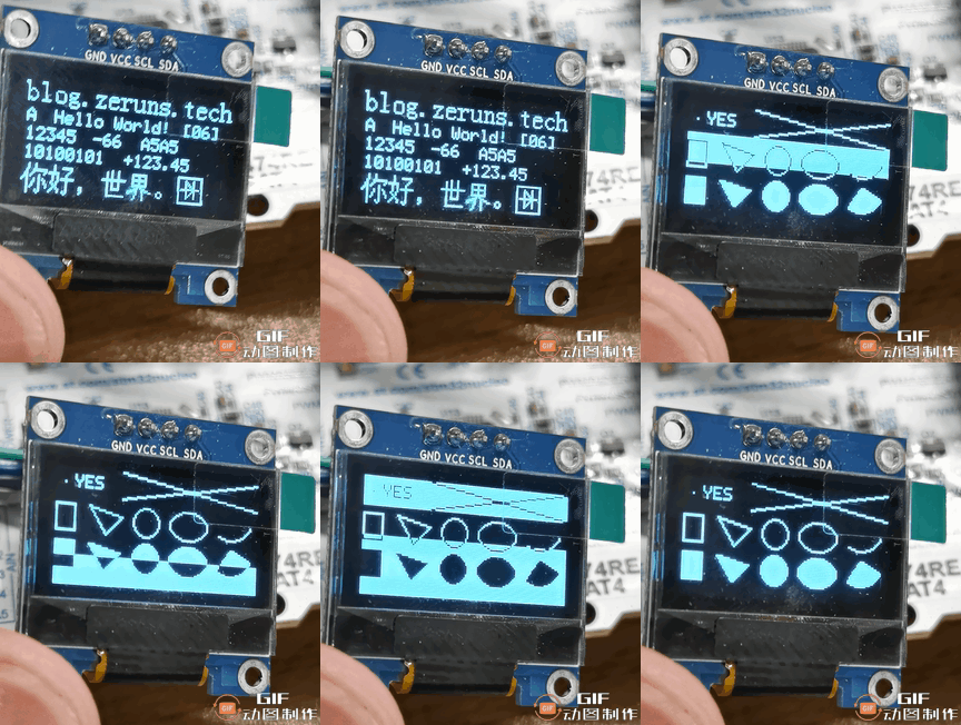
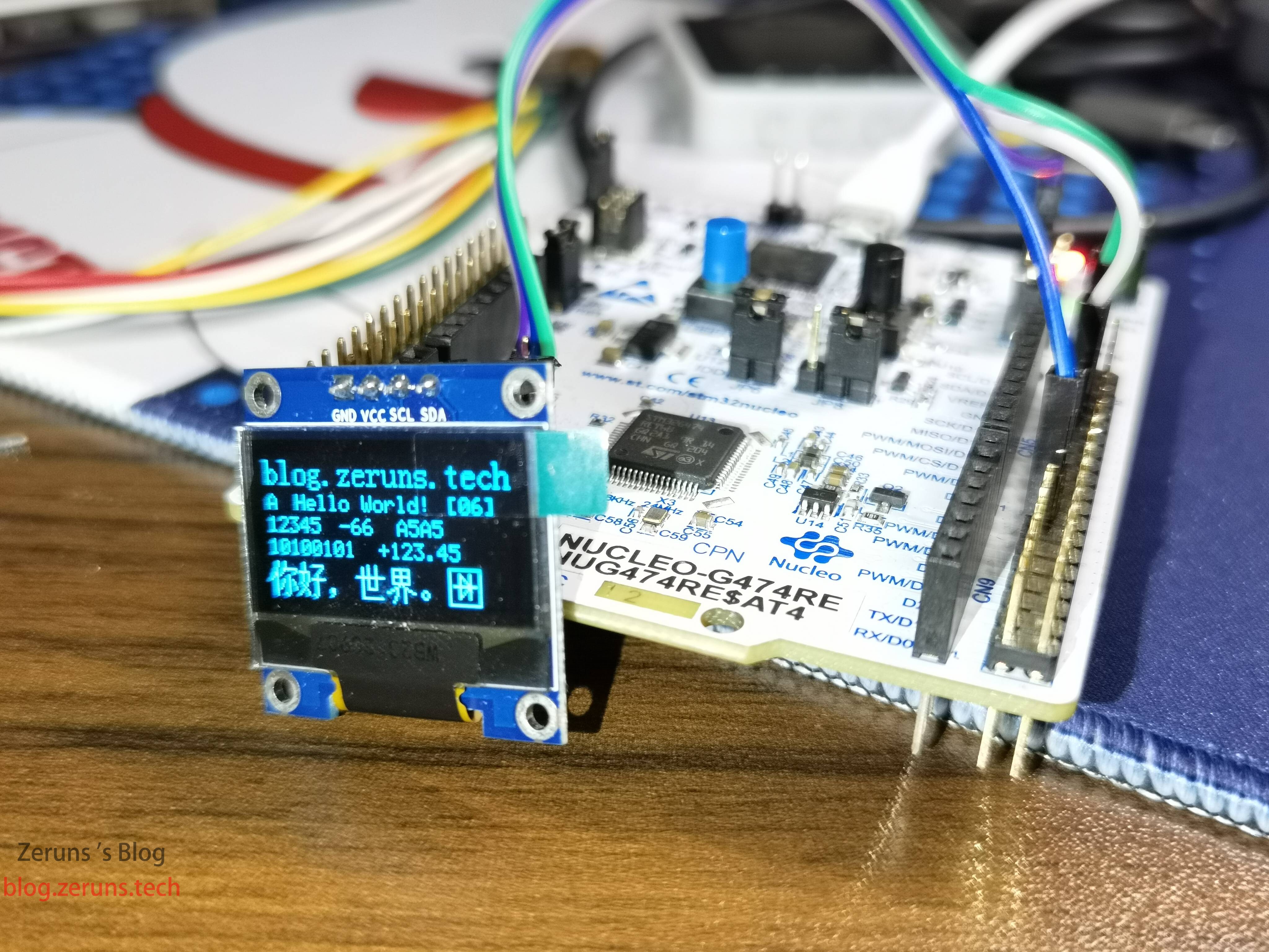
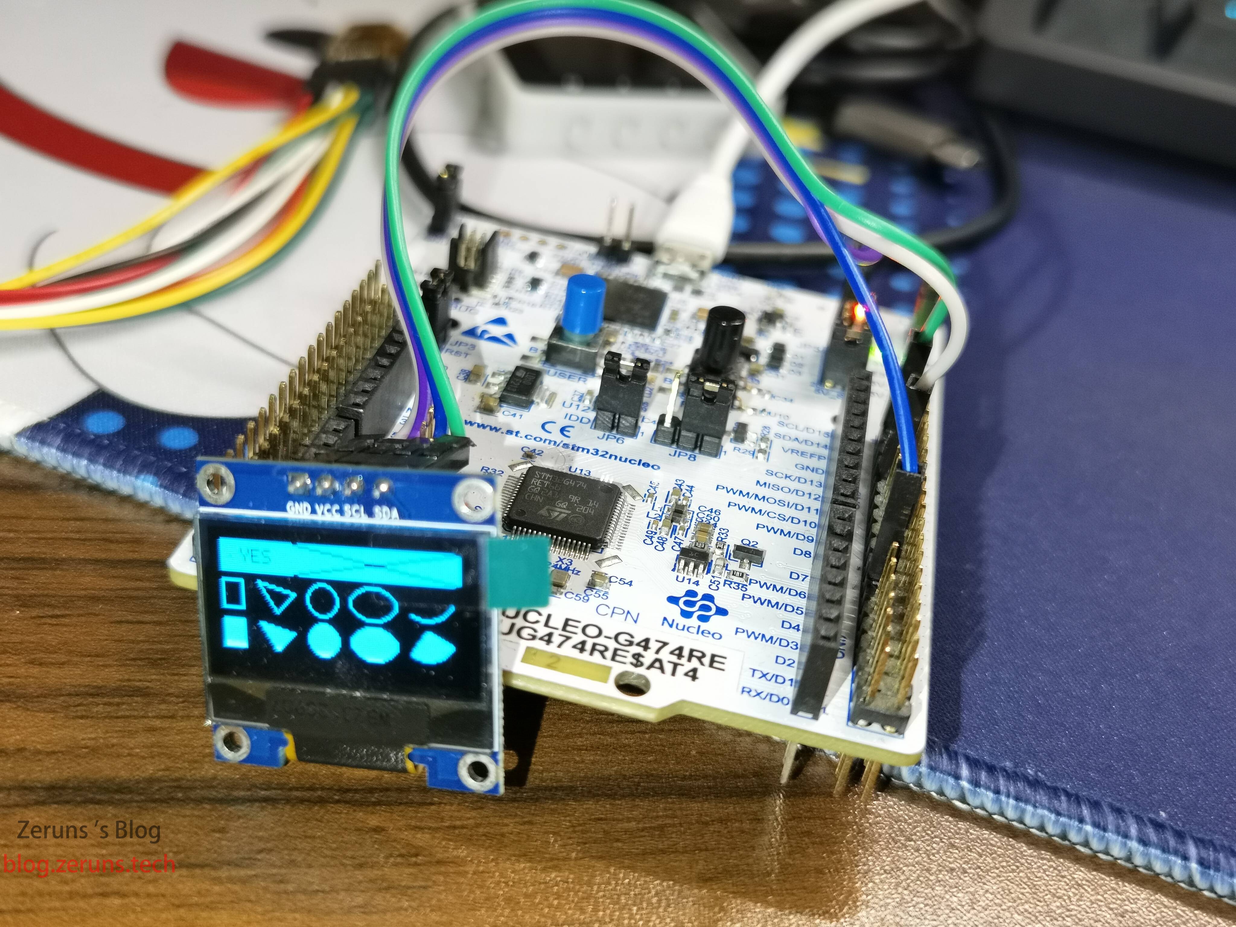
This driver is more complete, it can realize content display of English, integer, floating point, Chinese characters, images, binary numbers, hexadecimal numbers, etc. It can draw points, straight lines, rectangles, circles, ellipses, triangles, etc., and support multiple fonts, almost equivalent to a simple version of the Graphics Library.
The program is based on the secondary modification of the code of Jiangxie Technology, the original program is based on STM32F103, and only supports software I2C, I modified to support hardware I2C, you can also modify the macro definition to change to use software I2C.
Test hardware for the NUCLEO-G474RE development board
About the OLED driver principle, as well as the use of driver tutorials can see the video of Jiangxie Technology: https://url.zeruns.tech/L7j6y
- STM32 using hardware I2C to read SHTC3 temperature and humidity sensor: https://blog.zeruns.tech/archives/692.html
- STM32F407 standard library project template with U8g2 graphics library ported: https://blog.zeruns.tech/archives/722.html
- STM32F1 based 0.96" OLED display driver with hardware/software I2C support: https://blog.zeruns.tech/archives/769.html
Electronic / microcontroller technology exchange group: 820537762
Source Article URL:https://blog.zeruns.tech/archives/776.html
rendering
Introduction to I2C Protocol
I2C communication protocol (Inter-Integrated Circuit) was developed by Phiilps, because it has fewer pins, simple hardware implementation, strong scalability, and does not require external transceiver devices (those level conversion chips) such as USART, CAN and other communication protocols, it is now widely used in the system of multiple Nowadays, it is widely used in the communication between multiple integrated circuits (ICs) in a system.
I2C has only one data bus SDA (Serial Data Line), serial data bus, can only send data one by one, belongs to the serial communication, half-duplex communication.
Half-duplex communication: can be realized in both directions of communication, but not in both directions at the same time, you must take turns to alternate, in fact, can also be understood as a kind of switching direction of simplex communication, the same time must only be a direction of transmission, only a data line.
For the I2C communication protocol is divided into physical layer and protocol layer physical layer provides for the communication system with mechanical and electronic functions of the characteristics of the part (hardware), to ensure that the original data transmission in the physical media. The protocol layer specifies the communication logic and standardizes the data packetization and unpacketization criteria for both senders and receivers (software level).
I2C Physical Layer
Commonly used connection between I2C communication devices

(1) It is a bus that supports multiple devices. The term "bus" refers to a signal line shared by multiple devices. Multiple I2C communication devices can be connected to one I2C communication bus, supporting multiple communication masters and multiple communication slaves.
(2) An I2C bus uses only two bus lines, a bi-directional serial data line SDA (Serial Data Line) and a serial clock line SCL (Serial Clock Line). Data line that is used to indicate the data, the clock line is used to send and receive data synchronization
(3) The bus is connected to the power supply through a pull-up resistor. ** when the I2C device is idle will output a high resistance **, and when all devices are idle, all output a high resistance, ** by the pull-up resistor to pull the bus to a high level **.
The microcontroller GPIO port must be set to open-drain output for I2C communication, otherwise it may cause a short circuit.
For more I2C related information and usage of STM32 you can see this article: https://url.zeruns.tech/JC0Ah
There is also the STM32 Getting Started Tutorial from Jiangxie Technology: https://www.bilibili.com/video/BV1th411z7sn?p=31
I won't go into detail here.
Instructions for use
The project is created with Keil5 and developed with Vscode+EIDE, both software can open this project.
All project files are encoded in UTF-8, if you open them, you need to change the editor code to UTF-8.
Hardware I2C
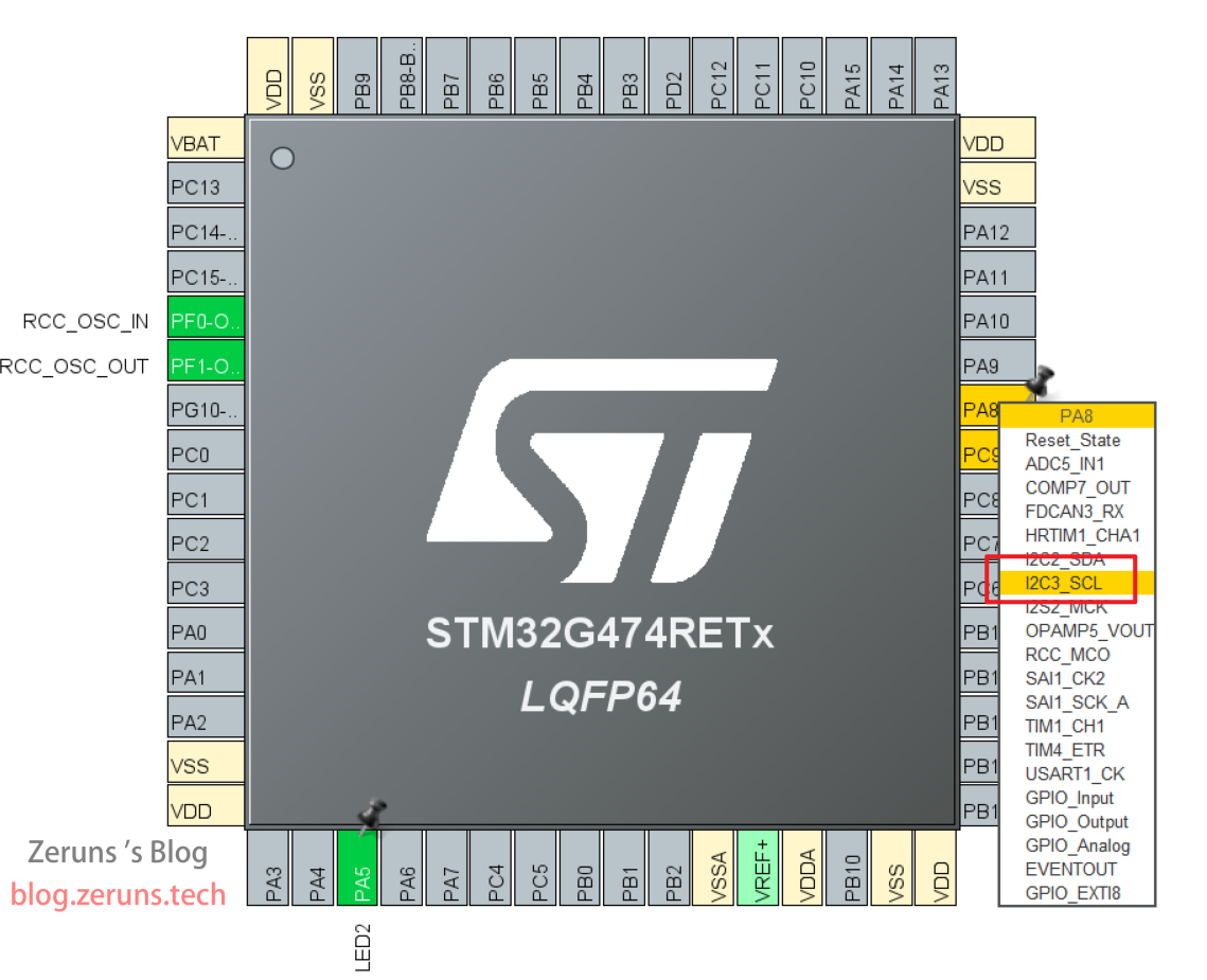
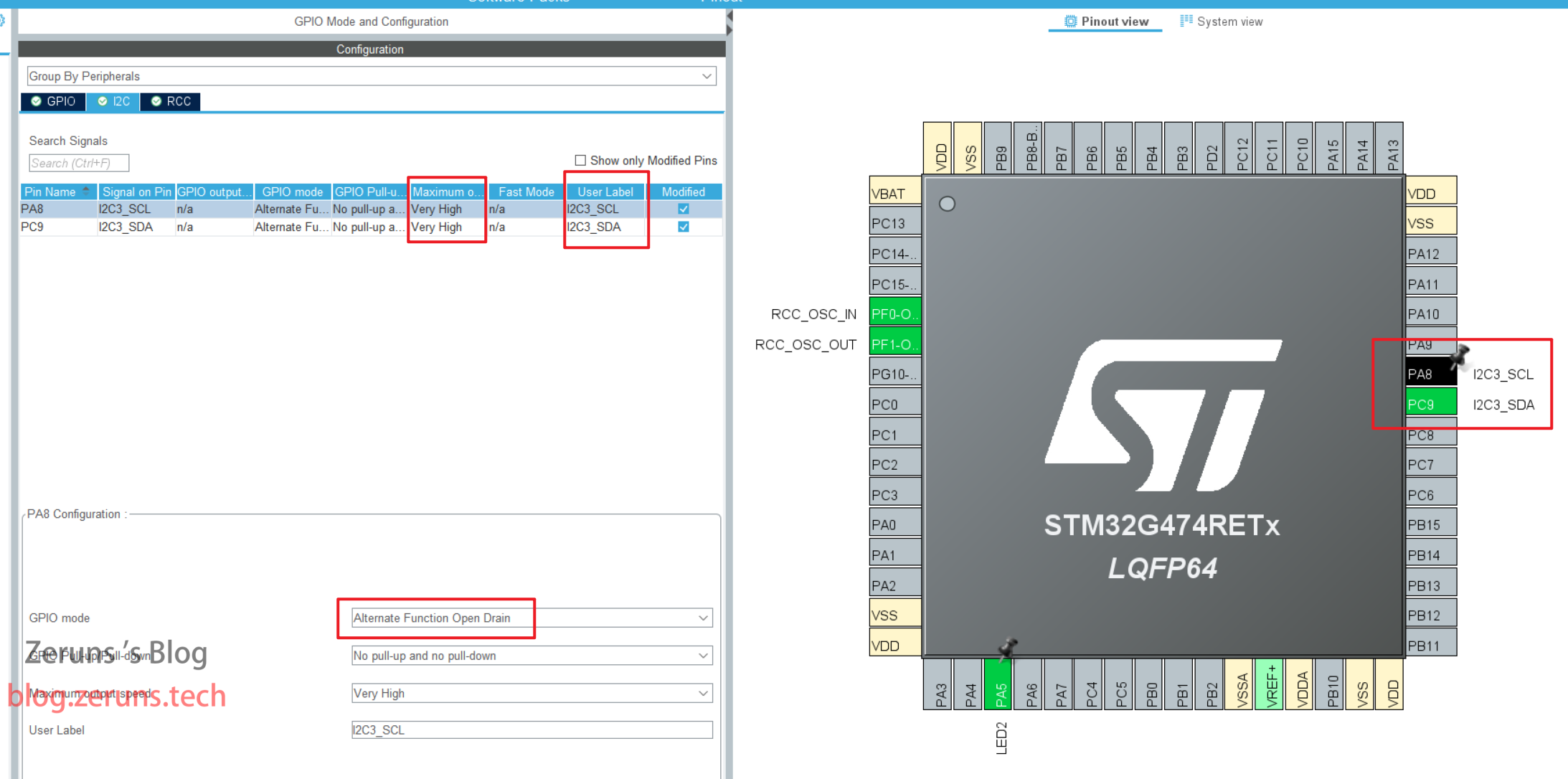
STM32CubeMX configuration, find the pin of the I2C peripheral you want to use, and set the pin function to SCL and SDA, the following picture shows the SCL of I2C3.
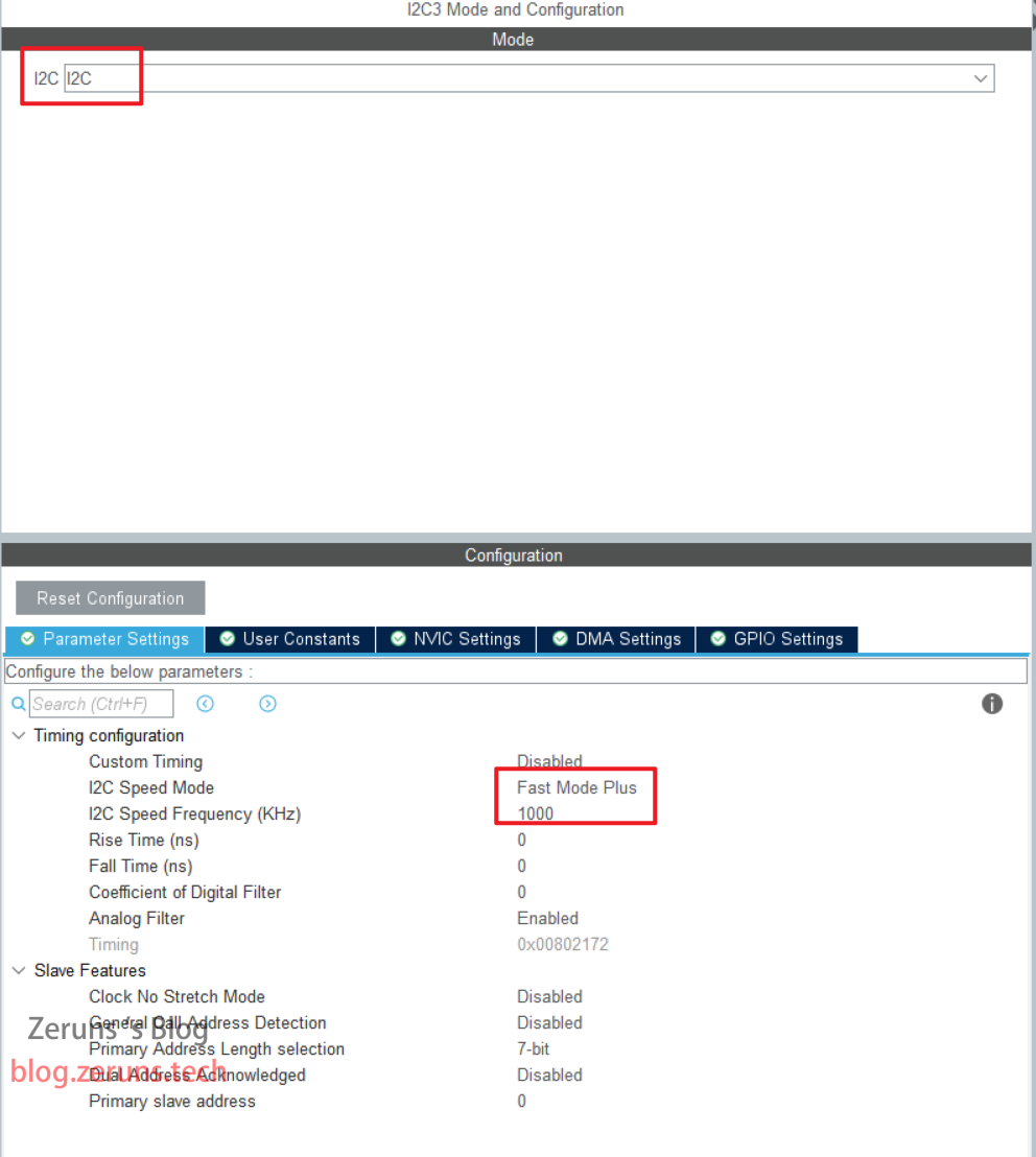
Next, configure the I2C peripheral, enable the corresponding I2C peripheral, set the speed mode to Fast Mode Plus, change the speed to 1000, and other defaults will work.
Configure GPIO, after the above setting, it will automatically configure those two pins as multiplexed open-drain output mode, then you only need to change the IO output speed to Very High, and the definition of GPIO label (User Label) to I2C3_SCL and I2C3_SDA respectively, on the line, if you are using other I2C, you can also set it to other values, the code should be modified at the corresponding place. If you are using other I2C, you can set it to other values, and change the code in the corresponding place. After changing the code, click Generate Code.
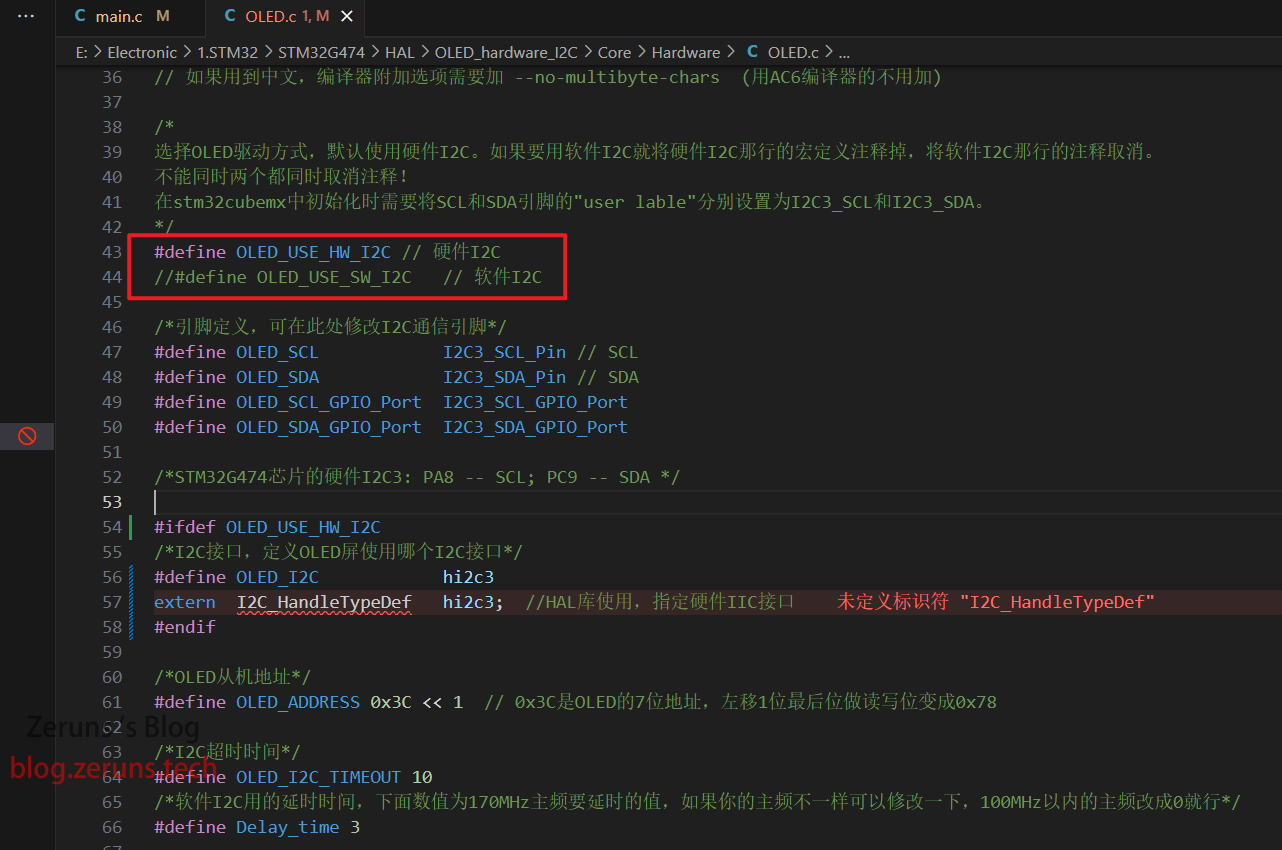
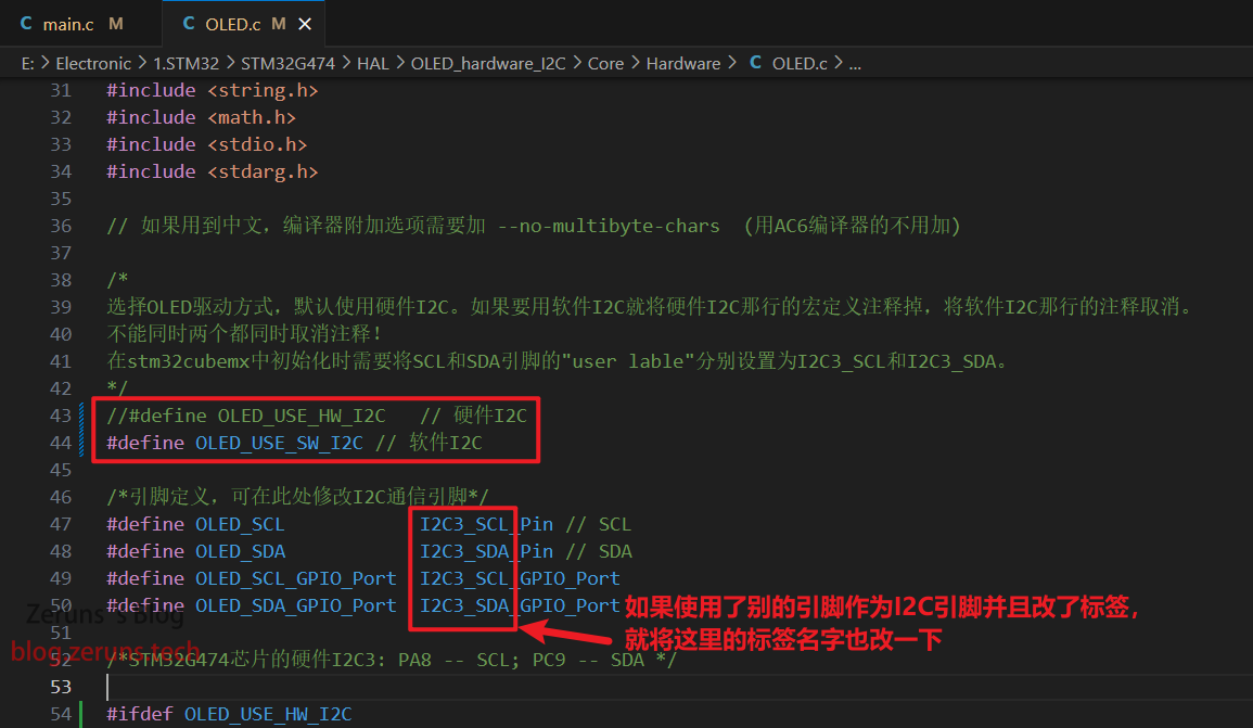
In the OLED.c file, comment out #define OLED_USE_SW_I2C, uncomment #define OLED_USE_HW_I2C, and change I2C3_SCL and I2C3_SDA in the code if you are using other I2C pins and have defined other names.
Software I2C
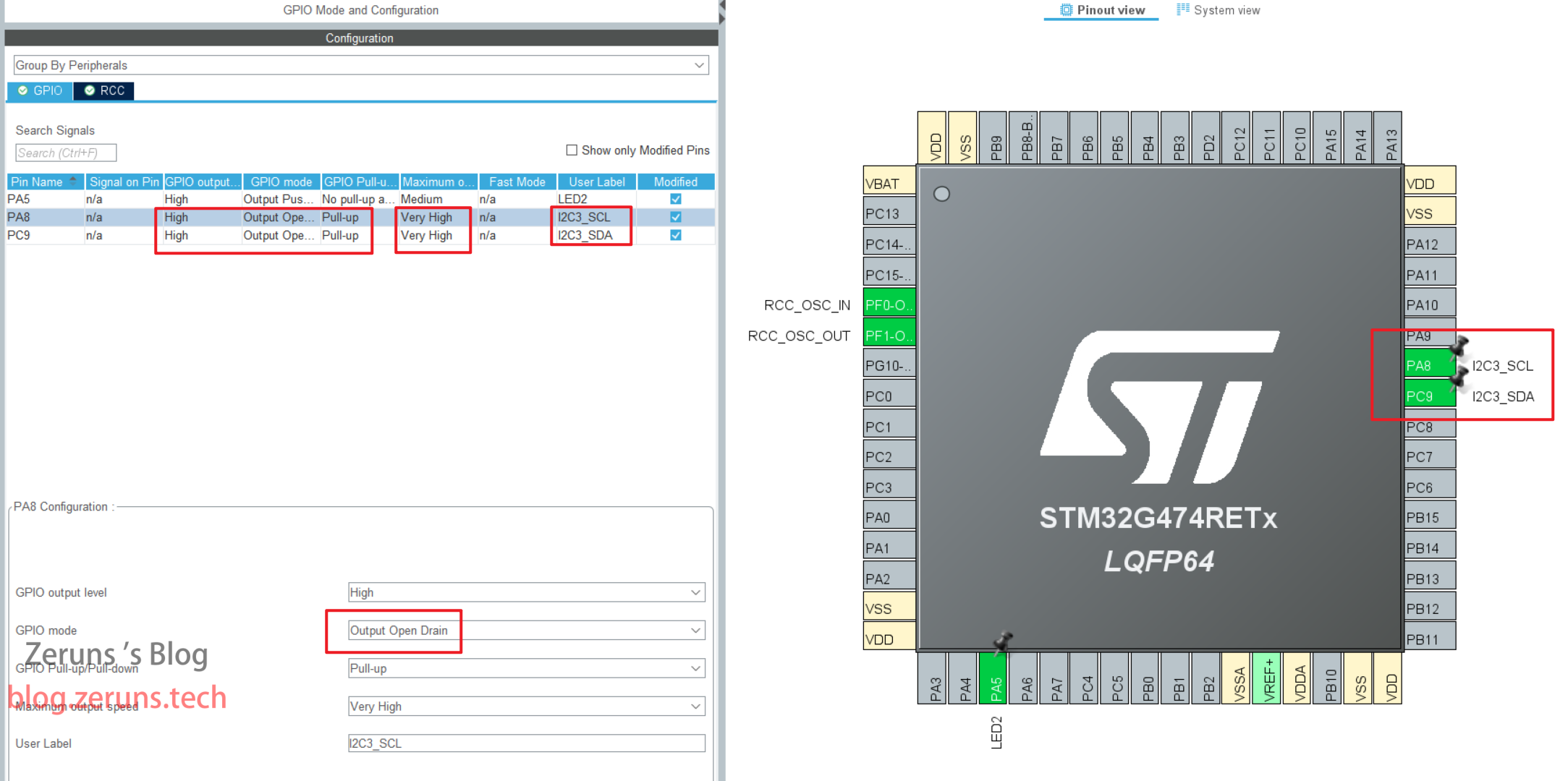
STM32CubeMX configuration, set two pins as SCL and SDA signal lines of I2C, modify the User Lable of IO port to I2C3_SCL and I2C3_SDA respectively, if you change it to something else, you need to change it in the code, the IO mode is set to open-drain output, the default output level is high, the output level of pull-up is high and the speed is set to the highest. The following figure shows. Click Generate Code after change.
In the OLED.c file, comment out #define OLED_USE_HW_I2C, uncomment #define OLED_USE_SW_I2C, and change I2C3_SCL and I2C3_SDA in the code if you use other pins as I2C pins and define other names.
需要用的元件
- STM32开发板入门套件:https://u.jd.com/fQS0YAe
- STM32G474开发板:https://s.click.taobao.com/8OwQ8vt
- OLED模块:https://s.click.taobao.com/EF0Evwt
- 杜邦线:https://s.click.taobao.com/VMkDvwt
- 面包板:https://s.click.taobao.com/bhg8Txt
- DAPLink(可代替ST-Link,带虚拟串口):https://s.click.taobao.com/QVQ8Txt
江协科技的STM32入门套件:https://s.click.taobao.com/NTn9Txt
推荐阅读
- 高性价比和便宜的VPS/云服务器推荐: https://blog.zeruns.tech/archives/383.html
- 做了个三相电量采集器开源出来,可以方便监测家里用电情况:https://blog.zeruns.tech/archives/771.html
- 我的世界开服教程:https://blog.zeruns.tech/tag/mc/
- 幻兽帕鲁开服教程:https://blog.zeruns.tech/tag/PalWorld/
- 睿登RD6012P数控可调电源简单开箱评测,60V 12A数控直流电源:https://blog.zeruns.tech/archives/740.html
- 拓竹P1SC 3D打印机开箱体验:https://blog.zeruns.tech/archives/770.html
- 不同品牌和种类的电容与电感实测对比(D值、Q值、ESR、X):https://blog.zeruns.tech/archives/765.html


Comment Section